Designs of copy milling machines for wood. How to make a homemade copy-milling machine (pantograph) for wood with your own hands
Execute copier lathe doing it yourself is not the most difficult task. But in order to achieve the desired result in terms of quality and efficiency, you will have to make some efforts. You will need it detailed drawing, a copy template and a few hours of free time. We offer you a version of a copier machine based on hand cutter as a cutting tool.

The proposed copier for your lathe requires little financial, time and labor costs. This is why it attracts a large number of craftsmen who need a copier for a lathe.
The cutting device will be a hand router. At the same time operational capabilities copiers directly depend on the characteristics of the turning equipment itself.
You should not count on the attractiveness of the design of a device you create yourself, since its main task is to create copies according to a template without unnecessary energy consumption.
The device of the machine with a copier

- To begin with, to create a lathe with a tracer, you will need a hand router. Choose its type yourself, depending on the planned work;
- The router is mounted on a support platform with dimensions of approximately 50 by 20 centimeters. It can be made from 12 mm thick plywood sheets;
- At your request copying machine can get a larger or smaller site. The dimensions largely depend on the parameters of the selected router;
- On the support platform, make holes through which the routers will come out;
- Holes for fastenings are also made here. It is optimal to use bolts as fasteners;
- Thrust bars located around the perimeter and fixed with self-tapping screws will provide protection against accidental movements of the cutter when processing products;
- Having installed the cutter support between the bars, make sure that it is securely fixed and there is no vibration or play;
- The far end of the support platform must be able to move along the guide pipe along the entire length of the turning equipment;
- Use a guide pipe with a diameter of 25 millimeters, or adapt it to your machine parameters;
- The main condition when choosing pipes is that they must cope with the loads from the weight of the router, not sag, and maintain an even, smooth surface;
- Secure the ends of the pipes with a pair of wooden blocks of a suitable size;
- The bars are mounted to the machine body with self-tapping screws or through bolts.
Installation of structural elements
In order for a lathe with a copier to work efficiently, and the copying process does not raise quality issues, do not rush in any case. It is precisely the rush that prevents craftsmen from making a really good copier for a lathe with their own hands.
Having studied the drawing on the basis of which you decided to build a copier with your own hands, stick to the suggested dimensions. If you make even a small error, the copying technology may be completely disrupted and the working axes may be disrupted.
To prevent anything like this from happening, follow a few important rules.
- The axis of the pipe intended for moving the router must be exactly parallel to the axis of rotation of the machine.
- The coincidence of the pipe axis and the machine axis is also an important plus, although this condition is not mandatory.
- The main point is the coincidence of the milling cutter in the lowest position with the axis of the turning device. This parameter is controlled and changed as necessary due to the level of placement of the copier.
- Fix the guide pipe through the blind holes of the wooden blocks. But immediately before fixing, place two bars on the pipe on which you plan to install the supporting platform.
- The wooden blocks for the load-bearing platform must move very easily, or rather slide along the guide pipe. If loosening is noticed, the copying unit will have to be redone.
Many fear the moment when increased demands are placed on gliding. But making a machine with such operating parameters is not difficult if you use an even, smooth pipe.
Horizontal bars
The next step is to install the horizontal wooden block, which is the second most important operating component of your lathe with a tracer.
- Adhere to similar precision requirements as in the operations described above;
- The horizontal beam is connected to the workpiece profile template;
- To make a block with your own hands, you can use a workpiece measuring 7 by 3 millimeters and fix it with self-tapping screws to the vertical posts;
- The wooden stands themselves are mounted to the lathe bed using any method convenient for you;
- Make sure that the top edge of the horizontal element is parallel to the axis of the machine and is located at the same level;
- If at some point you don’t need the copying functionality, you can easily remove the block with your own hands, fold the mounting platform onto the edge of the machine and use the turning unit for its intended purpose without a copier;
- A vertical stop is mounted to the milling table. A sheet of thin plywood is quite suitable here. Although if you require a more durable structure, use steel sheets;
- This element is used to move around the copier when sharpening parts. It sets the spatial position for the working milling cutter. Therefore, the copier should be fixed as securely as possible;
- Thickness plays an important role. The thinner the vertical stop is, the more accurately the lathe can copy your template. But even if the stop is too thin, the device begins to move according to the pattern with certain difficulties. Therefore, the optimal way out of the situation is to search for an intermediate option;
- If you use plywood to make a copier, be sure to consider using a removable structure. This will allow you to easily dismantle the copier when it wears out and replace it with a new one with minimal time investment.
Sample
The last but not least important element of a lathe with a copier function is the copy template itself. It is not difficult to make, but the configuration completely depends on the parameters of the products that you want to obtain using your machine.
- Take a sheet of plywood or OSB board;
- Apply markings on the sheet according to the contours of the future product that you want to turn on a lathe;
- Be sure to compare all dimensions with the required parameters;
- Use an electric jigsaw to carefully cut the blade along the contours, cutting out the required part;
- Finish the edges grinder or regular sandpaper. The template should not have any irregularities, burrs or nicks;
- Secure the resulting template to the horizontal rail using self-tapping screws;
- Carry out fixation strictly in accordance with the installation parameters.
Using drawings and video instructions, you can easily make a fairly efficient, productive copy lathe unit yourself. You just need a little patience and time.
IN modern world Often there is a need to create a copy of something or reproduce and repeat something. For this purpose, many enterprises widely use copy-milling machines, which are intended to create products whose shape most closely matches the given original sample. They make it possible to produce parts in large quantities, while ensuring high speed of processing and manufacturing of each element.
Features of the milling procedure
Milling is one of the common machining methods. Using milling, roughing, finishing and semi-finishing of shaped and simple surfaces of workpieces made of steel, non-ferrous metal, cast iron and plastics is carried out. Milling is characterized high level productivity, which allows the final result to obtain products of the correct geometric shape.
Milling can be carried out in two ways: the procedure of up milling (against the feed), when the feed is opposite to the direction of rotation of the cutter, and down milling (along the feed), when the directions of rotation of the cutter and feed coincide. Using cutters that are equipped with modern cutting materials (mineral ceramics, synthetic super-hard), you can process materials that are hardened to high hardness, thereby replacing the grinding procedure.

Milling machines are designed for milling the surfaces of levers, strips, housings, covers and brackets of simple configuration, complex configuration contours (such as templates, cams), surfaces of body parts. Milling machines are divided into two main categories: general-purpose machines and specialized machines. The first group includes longitudinal milling, cantilever, non-cantilever and continuous milling machines. The second category includes thread-milling, gear-milling, slot-milling, key-milling and copy-milling machines.
Purpose of a copy milling machine
Copy-milling machines are usually used to perform copying work in volume and on a plane, as well as in volume using three-dimensional models and corresponding copiers, for engraving various shaped profiles, patterns, ornaments and inscriptions, as well as for light milling work. The indisputable advantage of such units is that it is capable of performing with its own simple device incredibly complex patterns.
The machine can perform various milling operations on steel, cast iron and non-ferrous metals using high-speed and carbide tools in large- and small-scale production. On such machines, propellers of ships, blades of turbojet engines and steam turbines, impellers of hydraulic turbines, cutting and forging dies, press and casting molds, various cams, dies, molds, etc. are produced. metal models and blanks.

Such equipment is also used for drilling holes for handles, locks, latches, metal hinges, as well as making frames for mirrors and channels of any size on plastic and aluminum profiles, as in the video about copy-milling machines. On universal machines The processing procedure for such products is almost impossible.
Copy- milling machine is intended for milling curved parts using a copying technique according to a template from which the shape of the future product is copied. The use of templates allows you to eliminate such the most complex operation the influence of the human factor, and all finished parts as a result have the same shape.
To make several completely identical products, you can not only use a single template, but also make all subsequent parts based on the first one. However, for the most accurate repetition, it is recommended to supplement the machine with a copying device called a pantograph. Its design can be different, but the function is the same in all cases - to more accurately transmit the movement of the copying head along the profile to the cutting device.
Design of copy milling machine
The copy-milling machine is designed for processing profiles (planar milling) or reliefs (volume milling) of products using a carbide cutting tool - a milling cutter. The cutter reproduces on the product the contour or surface of the setting device - the copier. The driving device of a manual copy-milling machine has a pneumatic, mechanical or hydraulic connection with a tracking system, which is responsible for directing the cutting tool, on the one hand acting on the amplifying device, and on the other influencing the executive body.
A flat template, a spatial model, a reference part, a contour drawing can act as a copier, and a probe, a copy roller or finger, or a photocell can serve as a copy device. Copy samples can be made of metal, plastic or wood. The workpiece and the copier are mounted on a rotating table.

The executive body can be a spool, a screw, a solenoid, an electromagnetic clutch, or a differential. In the amplification devices of copy-milling machines, electromagnetic, hydraulic or electro-optical relays are used. The surface roughness of the workpiece and the accuracy of the profile depend on the speed of movement of the tracking device: roughness No. 6 and a profile accuracy of 0.02 millimeters are achieved. The actuator circuit is driven by a power hydraulic cylinder and an electric motor.
Copying at a specified scale is carried out using a special device called a pantograph. If you are interested in how to make a copy-milling machine yourself at home, then you can supplement it with this device. The pantograph has a structural guide pin, which is located on an axis and moves along the copier, a rotation axis and a tool spindle. When moving along the finger pattern on the workpiece, the spindle describes a geometrically similar figure. And the copying scale is determined by the proportions of the pantograph arms.
Types of copy milling machines
Based on the type of drive, the following main types of copy-milling machines are distinguished: with a pantograph, which is designed to work in 2 and 3 dimensions; universal devices with a pantograph, which is located on a rotating arm in a vertical plane; single and multi-spindle units with rectangular and round table; with mechanical feed, electrically and hydraulically, as well as photocopying.

There are several types of similar milling and copying machines, which differ in the level of automation and clamping of the workpiece being processed:
- Manual or desktop copy-milling machine with mechanical profile clamping. With its help, you can carry out the drilling procedure various shapes according to the template, however, for triple holes you will need a three-spindle attachment on a machine or drill.
- Automatic (stationary) milling and copying machine with pneumatic profile clamping. Such machines also do not allow triple holes to be made for installing handles and, as a rule, are used for the production of aluminum structures.
- Automatic (stationary) milling and copying machine with pneumatic profile clamping and a 3-spindle attachment for drilling triple holes.
Operating principle of a copy milling machine
Processing of products on a copy-milling machine is carried out using a master device (copier), the action of which causes, through the copy device, a corresponding movement relative to the workpiece of a special cutting tool. Through the copying device, the copier acts on the actuators, while the workpiece and the cutter recreate in relative motion the surface that is specified on the copier.
The main movements are rotation of the spindle, movement of the table and slide along the contour, and movement of the spindle head when cutting. Auxiliary movements - acceleration of movement of the slide, spindle head and table, installation movements on the table of the tracer table, stops, copying finger and clamping of the spindle head.

Copy milling machines for aluminum are capable of operating according to 2 tracking schemes: actions with feedback And simple action. The copy probe and the cutter in the simple-action scheme are rigidly connected to each other, and the movement of the probe along the copier is transmitted to the cutter. The deflection of the trace probe in a feedback circuit causes a mismatch in the position of the trace probe relative to the cutter.
The result of such a mismatch enters a special tracking system, which actuator issues a signal to adjust the tool path. In this case, there is no rigid connection between the cutter and the copier, and the copier does not perceive the cutting force, but only transmits the corresponding signal to the executive bodies.
There are two types of copy milling - volumetric and contour. When contour copying, the copier curve can be placed in a plane that is parallel or perpendicular to the axis of the cutter. In the first case, the table with the copier and the workpiece moves in the longitudinal direction; the change in the curve is controlled due to the vertical movement of the cut-in and the carbon finger. In the second case, the table with the copier and the workpiece moves in the transverse and longitudinal directions according to the shape of the curved line of the copier.

During volumetric copying, the complex spatial surface of a workpiece is processed with a cutter sequentially, through several parallel table strokes, that is, contour copying is performed with each working stroke. At the end of the pass, the cutter is shifted relative to the workpiece perpendicular to the line by the amount of the transverse feed, then the next working stroke occurs.
There are also direct-action copy-milling machines, in which the milling probe transmits movement through the pantograph. Such machines are mainly used for light engraving and milling work. When using a pantograph, in addition to copying, it is possible to reduce the scale of workpieces in relation to the copier. The movement of the copy probe along the copier, which is installed on the machine table, is transmitted to the spindle, which, when processing the workpiece, describes a contour similar geometrically to the copier.
Do-it-yourself copy-milling machine
Currently, the market offers milling and copying machines of the most different designs and level of difficulty. However, it is not always possible to buy one, and the price of a copy-milling machine is quite high. Therefore, we often face the question of how to make a copy-milling machine at home.
Undoubtedly, homemade machines cannot fully compete with industrial models, but they are still functional and allow the production of high-quality copies. I would like to immediately make a reservation that it will be very difficult to adapt a copying device to an industrial milling device, and this concerns, first of all, a radical redesign of the entire device. Therefore, the easiest way to assemble a homemade copy-milling machine is practically “from scratch” using a system of rods and electric motor with chuck for cutter.
There can be many designs of copy-milling machines. The typical design of the device is as follows: the machine structurally consists of a work table, a supporting frame and a milling head. The working surface can be adjusted in height, the milling head is equipped with an electric drive motor and a two-stage transmission mechanism that provides two speeds of the milling shaft.
Many homeowners complain that when copying a product, the resulting part has many flaws and inconsistencies that appeared when changing the direction of the cutter, vibration and trembling supporting structure. Adding to the troubles are sagging and curvature of the workpiece, which are associated with an increase in internal tension due to tree sampling. It is impossible to avoid all the shortcomings when making a homemade copy-milling machine. It is simply recommended to make the copying machine narrow-profile, and not universal.

A homemade copy-milling machine should be optimized for the production of specific products that you need. For example, to efficiently manufacture a wooden part of a gun and a propeller screw, different technical solutions, they cannot be combined in one machine, and side effects that are difficult to correct may occur. Thus, it is more practical to assemble machines for specific tasks. This approach can save you many costs and difficulties.
An important factor is the size of the machine. The larger the product you plan to process, the more massive the structure should be. It is necessary that the vibrations transmitted from the cutter drive are absorbed by the weight of the machine's supporting structure. Loads must be supported by guide axes, which must also have a safety margin and not bend. The optimal parameters when designing a copy-milling machine with your own hands are selected experimentally, this ensures smooth operation of the cutter.

When designing a copy-milling machine, determine the type of parts you will produce. To perform engraving work and to mill long products, a different work table and a method for securing workpieces with a template on it are required. Freedom of movement in different planes of the cutting tool depends on the type of work table.
The power of the electric motor, which rotates the cutter and is installed on a homemade copy-milling machine, depends on the parts being manufactured and their material. For engraving and milling wooden products A 150-200 watt DC electric motor is sufficient.
To ensure an accurate copying procedure, you need to rigidly connect the copying probe and the device to each other, securing the cutting tool in it. In this case, their height and planes above the desktop must coincide completely. The created rigid structure should be installed above the desktop in such a way that it can move in the vertical and horizontal plane along the axes that are conventionally created by the sides of the desktop.
The Duplicarver copy-milling machine is used for copying sculptures and flat-relief products, as well as wood carvings. Today, analogues of such technology are Russian market No. The equipment has received recognition among specialists and novice craftsmen. This device complies with the requirements of technical regulations.
There are three types of machines on sale:
- "Duplicarver-1";
- "Duplicarver-2";
- "Duplicarver-3".
With their help, you can carry out not only cultural and volumetric carving, but also flat-relief work. These can be panels, as well as panels of small depth. The dimensions of the products are determined by the width, and their length can be any. “Duplicarver-3” retained all the characteristics of “Duplicarver-2” and acquired new ones. With its help you can carry out long volumetric threads.
The working tool of the device is a high-quality milling cutter, which is manufactured in Germany. The machine works accurately and as reliably as possible, and you can master the techniques of working with it quite quickly. If you cannot afford such equipment, then you can make copy-milling machines for wood yourself. To do this, there is no need to purchase any complex spare parts.
Classification by degree of automation
When copy-milling machines for wood are made, initially the craftsmen understand the varieties of such equipment, it can be
- desktop or handheld;
- automatic;
- stationary.
In the first case, the workpiece is fixed mechanically; holes are usually drilled on these devices different shapes, however the parameters are affected by the template. Stationary automatic equipment fixes workpieces using pneumatic clamps; it can work with aluminum.
When preparing drawings of a milling and copying machine before its manufacture, you must also understand that there is stationary automatic equipment with pneumatic clamps, which are complemented by three-spindle heads.

Homemade equipment can be created according to a drawing. As a result, you will be able to get a device that performs its tasks, just like factory equipment. The copier will consist of the following components:
- work surface;
- device for installing a router;
- supporting frame.
When they are manufactured they have a milling head, it should be supplemented with a transmission mechanism and electric motor, this is the only way to achieve multiple speeds. As a result of using such a unit, it is possible to produce a part that may have a number of flaws.
They can occur during the process of changing the direction of the cutter, vibration and trembling of the structure. Inconsistency can also occur due to the curvature of the part; this problem occurs when there is internal stress. You can eliminate shortcomings by making a machine to produce parts of a certain type.
Features of creating a copier

If you decide to make a copy-milling machine yourself, then it should be optimized for processing specific parts. An important factor to consider when self-production machine, is total weight. This should also include the dimensions of the structure.
It should be more massive if you plan to process large-sized products. This allows the equipment to reduce vibrations that occur during cutter operation. The guide axles should be made with a significant reserve of power, only then will they not bend under increased loads.

When making a copy-milling machine with your own hands, it is important to understand its design features. The system will have a working head and a supporting frame. The working surface can be adjusted in height, while the milling head must be supplemented with a two-stage transmission mechanism that provides two shaft speeds.
Making a pantograph

Copy-milling machines for wood have a pantograph as their main unit, which can be made of wood. However, you should be prepared for the fact that high precision it will not be possible to achieve in this case, because the connection of wooden blanks is carried out using hinges.
If you use loops to fix them, a backlash will form between them. Metal is sometimes used to make a drawing pantograph; it can be used to create copies on different scales, but it can only be used to create three-dimensional copies.
Work methodology

The working element can also be connected to each other using pneumatic, hydraulic or mechanical elements, which are required to generate the force from the copier to the working element. The template can be a flat contour or spatial model. You can use contour drawings, a reference part, but the element for reading the dimensions and shape will be a copy roller or finger, photocells or a probe.
You can use wood, plastic or metal for the template. This unit must be located on a rotating work table of the equipment. When CNC milling and copying machines are manufactured, they must have a working element that begins to move thanks to a solenoid, spool valve or relays are located in the amplification devices, they can be hydraulic, electromagnetic or electro-optical.
Features of manufacturing copy-milling turning equipment
The copier will work, providing quality depending on the speed of movement of the tracking device. The actuator circuit will have a main element in the form of a hydraulic cylinder or an electric motor. The guide pin will make up the pantograph structure. It is necessary to place the guide pin and spindle on the same rail.
The rail must have shoulders, the ratio of which will determine the scale of copying. The copying machine will have a finger that will move along the contour of the templates. He will be responsible for the movement of the rack, which rotates freely on the axis. On the other side of the rack, the spindle will make identical movements when processing parts. On such machines, the described device will not be superfluous, and its presence will increase functionality.
Conclusion
Copy-milling machines have gained great popularity among consumers today for the reason that in everyday life and in production there is often a need to create copies or repeat products. For this purpose, devices are used today that provide high productivity and accuracy, which cannot be achieved manually.
Milling is a type of mechanical processing of materials using a special cutting tool - a milling cutter. The method allows you to obtain a high level of accuracy and the degree of roughness of the processed surface. In addition, it is distinguished by significant productivity.
Surface processing is carried out by the method of up milling, when the rotation of the cutting tool is opposite to the direction of feed, and by down milling - a method in which the direction of rotation of the cutter and feed are identical. By using cutters with cutting edges made from modern super-hard materials, the grinding operation can be replaced.
Milling equipment is divided into universal and specialized. In the first case, these are general-purpose machines for performing longitudinal and continuous milling, with or without tools mounted on a console. The second contains a mechanism for cutting threads, splines, making gears and keyways, and pattern milling.
In production, there is often a need to produce several pieces, a batch, or even a series of identical parts. For this they use milling equipment, equipped with a pantograph.
IN household The functions of a milling machine are usually performed by a manual milling machine. To perform the maximum range of work, the milling cutter is equipped with a whole set of accessories. The main equipment is supplied with the equipment, additional equipment can be purchased or manufactured independently. These are a variety of stops, clamps, templates. But you can go even further and make a copier for milling volumetric parts.
Milling and copying equipment: operating principle
The operating principle of such a device is to clearly transmit the movements of the copy head through the holder profile to the cutting tool.
It is quite difficult to purchase a copy milling machine, so craftsmen They make it with their own hands from scrap materials. Everything happens by trial and error. Therefore, experts advise first assembling a duplicate carver, and only then introducing it into mass production. As a rule, this stage is preceded by more than one serious adjustment and alteration.
Milling and copying equipment: areas of application
Milling copying machines can process not only flat, but also three-dimensional parts. With their help, along with simple milling operations, you can perform engraving, repeat drawings, patterns and inscriptions. The design of the machine is quite simple, and any craftsman can make it.
Copy-milling machines allow you to process not only wooden parts, but also cast iron, steel and plastic workpieces, as well as products made of non-ferrous metals. This is ensured by high-quality tools made of high-speed steel and hard alloys. The copying machine allows you to mill not only straight, but also curved surfaces. In this case, the details are completely identical.
Milling and copying equipment: design
The typical design of a copy-milling machine is completely simple. It consists of a work table and a guide system with clamps for attaching the router and copier.
Making a universal copy-milling machine at home is quite difficult, and there is not much need for it. For home use, equipment with highly specialized specialization is usually created.

Manufacturing of copy milling machine: materials
To create a duplicate carver at home with your own hands, you should draw a basic sketch, which will become a guide to further actions. In addition, you need to stock up on some materials. This:
- Knee cemented polished shaft Ø 16 mm.
- Linear bearings in the amount of 2 pcs.
- Rail guides 900 mm long – 2 pcs. For ease of fastening, their length is taken as a multiple of 150.
- Split linear bearings in the amount of 4 pcs. It is advisable to use bearings with a clamping screw to adjust the tightness of the fit on the guide.
- Profile pipe 30×60 with wall thickness up to 3 mm.
- Metal plate 900 mm long and 100 mm wide.
- End posts in the amount of 2 pcs.
- Moving element in the form of a plate – 1 pc.
- Rocker arm for attaching the copier and router – 2 pcs. The length is chosen arbitrarily.
- Movable couplings – 2 pcs.
- Profile pipe 40×40 with a wall thickness of up to 3 mm.
- Crown clutch for turning the part and template.
Making a copy-milling machine: tools
After this, you need to prepare a tool that will definitely be useful for assembling the machine structure. This:
- angle grinder;
- cutting and cleaning disc;
- welding machine;
- welding mask;
- petal disc or brush;
- self-tapping screws for fastening rail guides and moving elements;
- electric drill;
- screwdriver;
- measuring instruments: tape measure, caliper;
- center punch and scriber.
Making a copy-milling machine: step-by-step instructions
After everything is ready, the actual assembly of the copy-milling machine begins.
Step #1
It is necessary to cut two pieces 950 mm long from a 30×60 profile pipe to attach the rail guides. A margin of 50 mm is needed for installing limit switches in order to prevent linear bearings from slipping off.
Step #2
The 40×40 profile pipe needs to be cut into blanks for the base. Guided by the existing sketch, you need to cut two pieces of 1350 mm and two pieces of 900 mm.
Step #3
It is necessary to cut small racks from the same pipe. Their linear size depends on the height of the subsequently processed parts.
Step #4
Now you need to remove the rust from the pipes. To do this, you can use a flap disc or brush.
Important! Before using the brush, pay attention to maximum quantity working speed on it and the grinder. The rotation speed on the brush must exceed the speed of the equipment.
Step #5
After this, we weld all the joints and clean the seams with a 6 mm thick cleaning wheel.
Step #6
Then it is necessary to ensure parallelism of the rail guides. To do this, you need to make the connection between the rack and the base of the rail guide detachable. It is necessary to take a washer according to the internal size of the rack, weld a nut to it and screw in the bolt. The bolt at this stage is needed in order to install the nut and washer in the cavity of the stand pipe flush and in strict vertical position, and when welding it, do not damage the thread. This must be done with all four racks.
Step #7
Weld the posts to the base.
Step #8
At the base of the rail guide, at the junction with the racks, you need to drill holes: in the upper shelf for the bolt head, in the lower one for the thread.
Step #9
Install the rail guides on the base (30×60 pipe), pre-drilling holes, and secure with metal screws.
Step #10
Install the bases with rail guides and tighten with bolts.
Step #11
Check the parallelism of the guides. If it is missing, it is necessary to make adjustments by placing foil of different thicknesses on the racks under the guide.
Step #12
On the metal plate you need to mark and drill holes for attaching split linear bearings and end posts.
Step #13
After this, you need to make a movable element by welding 300 mm long rocker arms for the feeler gauge and router to a metal plate, then attach linear bearings to it.
Step #14
After this, the moving element must be placed on a polished shaft, along the edges of which the end posts must be installed.
Step #15
The entire structure must be installed on a metal plate 100 mm wide and the end posts must be secured with self-tapping screws.
Step #16
Then, split linear bearings must be installed on the metal plate on the bottom side.
Step #17
After this, the suspended structure is put on the rail guides with split bearings and the end switches are installed.
Step #18
Movable couplings are installed at the end of the rocker arms and a probe and a milling cutter are attached.
Step #19
In order for the workpiece and the part to rotate synchronously, it is necessary to connect them with couplings. A sprocket and crown are suitable for control. The copy milling machine is ready. The design achieved 5 degrees of freedom. Movement along the X axis is ensured by the movement of the structure along rail guides, movement along the Y axis is ensured by the movement of a moving element along a polished shaft, and movement along the Z axis is ensured by the movement of rocker arms.
Additionally, due to the movable couplings, the probe and the milling cutter can move left and right along the axis of the rocker arm, and it is possible to move the template and the workpiece simultaneously. This makes it possible to process parts of almost any shape.
Copy-milling machines for metal in mass and serial production
Metal copying and milling machines are used in mass production. With their help, ridge propellers for ships, jet engine turbines, pump impellers, dies for forging and press production, and blanks for mechanical and foundry production are manufactured. In everyday life, metal copying equipment is practically not used.
Pantograph for a router: design features
To scale copying processes, there is a special device called a pantograph. It facilitates the manufacturing processes of parts with curved surfaces, allows you to create ornaments and patterns of any complexity in a reduced form. The cost of such a device is quite high. But making a pantograph at home with your own hands is quite possible.
Pantograph for a router: principle of operation
The schematic diagram of a pantograph looks quite simple. It is a square divided in half. All joints are hinged, so all sides are movable, and the square easily turns into a rhombus when impacted. The zero point, located in one of the corners of the square, is fixed rigidly. Relatively, its design can be modified, turning into a rhombus. A cutting tool is installed in the middle of the square. A copier is fixed diagonally in the opposite corner of the square. The distance from the zero point to the cutter is a certain value A, and to the copier 2A. This gives a 2:1 scale. Linear size The long and short sides of the pantograph should also differ from each other by 2 times.
Pantograph for a router: materials
In order to make a pantograph with your own hands, you will need the following materials:
- Square metal profile 12×12
- Bearing 180201.
- Bushings for the outer race of the bearing.
- Pins according to the internal size of the bearing and M12 thread.
- Nut M12.
- Bolts M6×45
- Nuts M6.
- Bushing for securing the copier.
- Profile pipe 40×40
- Loop metal-plastic window.
- Dye.
- Masking tape.
- Metal plate.
- Screw for fixing the copier.
Pantograph for router: tool
In addition to the materials listed, you will need the following tools:
- Manual milling machine.
- Angle grinder.
- Welding machine.
- Wrenches.
- Measuring tool.
Pantograph for a router: step-by-step instructions for making it yourself
We proceed to the actual production of the pantograph.
Stage No. 1. Workpiece cutting
It is necessary to mark and cut the square profile according to the calculated dimensions. For convenience, you can use masking tape and metal plate. The tape will allow for clear markings, and the plate will help make an even and high-quality cut. The blanks for the platform for the router must be cut at a right angle, and the sections of the profile for the connecting rods must be beveled for maximum fit of the bearing sleeve.
Stage No. 2. Drilling technological holes
All workpieces must be chamfered and holes Ø 6.2 mm drilled for further connection into the structure.
Stage No. 3. Welding the platform for the router
After this, you need to weld the platform for the router.
Stage No. 4. Manufacturing of connecting rods
It is necessary to make something like a jig on the board and firmly fasten all the parts to be welded. To do this, a hole is drilled in the board, and the bearing in the bushing is clamped with a bolt, the square profiles of the connecting rods are secured with clamps. First, you need to insert two washers between them and fasten them with bolts. After this, all joints of the structure are scalded and cleaned. Then you need to cut the bearing sleeve between the square profiles on each connecting rod. M6 bolts, washers and bearings must be removed. It is necessary to weld a mount for the router onto the frame, and an extension for scaling onto the short connecting rod at the point opposite the zero point. The connecting rods can be painted to give an aesthetic appearance.
Stage No. 5. Making a unit for attaching a copier
Now you need to machine two bushings with internal diameter, similar to the size of the copier. Drill a hole on the side and cut a thread to install the screw that secures the copier. After this, you need to cut two pieces of 12x12 squares 20-30 mm long and weld them on the side between the bushings. The size between squares should be 12 mm.
Stage No. 6. Manufacturing of the bearing lifting mechanism
It is necessary to manufacture a bearing lifting unit. To do this, the zero point finger must be welded onto a piece of 12×12 profile and secured to a 40×40 profile pipe using a loop from a metal-plastic window. The profile pipe will serve as a place for attaching the pantograph to the table with a clamp.
Stage No. 7. Pantograph assembly
The bearings must be installed in the bushings and secured securely by tightening the square profiles of the connecting rods with M6 bolts. Using your fingers, you need to assemble the connecting rods into a single structure. Secure the pantograph to the table with a clamp and install the router. The device is ready for use.
Cutting tools for milling work: copy cutters
Copy cutters are a tool on which, in addition to the cutting part, there is a bearing. Its size is equal to the diameter of the cutting part of the cutter. The bearing can be located either in the upper or lower part of the cutter. This is how the tool is classified. It is worth considering that the marking indicates the position of the bearing in the usual placement of the cutter - with the shank up.
They are used to perform copying work according to a template. When using a cutter with an upper bearing, the template is located on top of the part; if with a lower bearing position, then from the bottom.
Job manual router involves the use of any cutters. It's safe. The only thing is that when using a cutting tool with an upper bearing, you should pay attention to the overhang of the cutter so as not to damage the workbench.
Milling on a woodworking machine involves using cutters only with a lower bearing position. This is due to the fact that a cutter with an upper bearing position has an open rotating cutting part in the workpiece area. Careless movement may result in serious injury. Such cutters are used on machines only in special cases with maximum compliance with safety regulations.
Copy milling machines are unique equipment that is used to perform the most complex work for the production of identical parts. But for working at home, you can make simple analogues of such equipment and devices that will help in your home or small business.
Making a simple copying machine with your own hands at first glance seems like an easy task. There are many photos of finished structures on the Internet that impress with their originality and ease of manufacture. Many people are eager to do something like this. But when the homemade copying machine is assembled, it turns out that not everything is so smooth.
Copying machines come with milling and turning. In terms of prevalence, the first place is occupied by milling and copying machines. They are more functional and allow you to get not only round copies, but also free-form copies. They will be discussed in this article.
The biggest problem with a home-assembled milling and copying machine is backlash and vibration. Many home craftsmen complain that when copying a sample, the resulting product has many inconsistencies and flaws that appeared when the direction of the molding cutter changed and the supporting structure shook. In addition, they add to the trouble of bending and sagging of the workpiece, associated with an increase in internal stress due to wood sampling. Therefore, when making a copying machine, it is impossible to immediately avoid all the shortcomings. As a rule, after assembly it is necessary to bring the structure to acceptable parameters for some time.
In any case, it is better to make a homemade copying machine not universal, but narrow-profile, that is, optimized for the manufacture of specific products that you need. For example, in order to effectively produce a wooden part of a gun, a screw for a propeller and voluminous text, different technical solutions are needed, and if they are combined in one machine, problems may arise. side effects, which will be difficult to fix. Therefore, it is more practical to assemble machines for a specific task. This approach will avoid many difficulties and unjustified costs.
The size of the machine is also an important factor. The larger the workpiece you plan to process, the more massive the structure should be. Vibrations transmitted from the cutter drive must be absorbed by the mass of the machine's supporting structure. And the guide axles must not only withstand the load, but also have a margin of safety so that they do not bend. When independently designing a milling and copying machine, the optimal parameters for the smooth running of the cutter are selected experimentally.
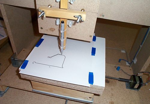
 The principle of operation of a milling and copying machine is as follows: a milling cutter for sampling wood and a probe are installed on a movable frame, which is used to guide the original. The frame lowers to wooden blank, and the milling cutter removes excess wood. The whole point of the design is to ensure simultaneous movement of the cutter and probe in three planes, as well as rotation around the transverse axis. For this purpose, metal guides or wooden hinge systems are used. Wood absorbs vibrations better, is easier to process and has a lower cost. The video at the bottom of the page shows a homemade copying machine for creating flat-relief images and three-dimensional inscriptions with in a non-standard way movement in space. Moreover, this design provides for a twofold reduction in scale. You can download the drawings of the milling and copying machine in one archive at the bottom of the page.
Now making a copy of, for example, a three-dimensional inscription will not be difficult. You can also make a template for creating 3D text yourself. To do this you will need a printed sketch, a couple of cardboard sheets, glue and a stationery knife. We glue the sheet with the sketch and the cardboard together so that the paper does not wrinkle. After drying, use the edge of a stationery knife to carefully cut out the letters exactly according to the sketch. A template height of 2 mm is usually enough to prevent the probe from slipping.