General techniques and rules for manual filing. Filing
Filing is a cutting method in which a layer of material is removed from the surface of the workpiece using a file.
A file is a multi-edged cutting tool that provides relatively high accuracy and low roughness of the processed surface of the workpiece (part).
By filing, parts are given the required shape and size, parts are adjusted to each other during assembly, and other work is performed. Using files, planes, curved surfaces, grooves, grooves, holes of various shapes, surfaces located at different angles, etc. are processed.
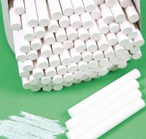
File(Fig. 1, A) is a steel bar of a certain profile and length, on the surface of which there is a notch
Fig. 1. Files:
A- main parts (1 - handle; 2 - shank; 3 - ring; 4 - heel; 5 - edge;
6 - notch; 7 - rib; 8 - nose); b- single notch; V - double notch;
G - rasp notch; d - arc notch; e - pen attachment; and - Removing the file handle.
The notch forms small and sharp teeth, having a wedge-shaped cross section. For files with a notched tooth, the sharpening angle β is usually 70°, the rake angle γ is up to 16°, and the rear angle α is from 32 to 40°.
The notch can be single (simple), double (cross), rasp (point) or arc (Fig. 1, b - d).
Single cut files remove wide shavings, equal to the length the entire notch. They are used for filing soft metals.
Double cut files used when filing steel, cast iron and other hard materials, since the cross cut crushes the chips, which makes the work easier.
Files with rasp cut, Having spacious recesses between the teeth, which contributes to better placement of chips, very soft metals and non-metallic materials are processed.
Arc cut files have large cavities between the teeth, which ensures high performance and good quality processed surfaces.
Files are made from U13 or U13 A steel. After cutting the teeth, the files are subjected to heat treatment,
File handles usually made from wood (birch, maple, ash and other species). Techniques for attaching handles are shown in Figure 1. e And and.
According to their purpose, files are divided into the following groups: general purpose, special purpose, needle files, rasps, machine files.

Rice. 2. Shapes of file sections:
A And b- flat; V - square; G- triangular; d - round; e- semicircular;
and - rhombic; h - hacksaws.
Improving conditions and increasing labor productivity when filing metal is achieved through the use of mechanized (electric and pneumatic) files.
In training workshops, it is possible to use mechanized manual filing machines, which are widely used in production.
Universal grinder(see Fig. 4, G), powered by an asynchronous electric motor 1, has a spindle to which a flexible shaft is attached 2 with holder 3 for securing the working tool, and interchangeable straight and angular heads, allowing, using round shaped files, filing in hard to reach places and from different angles.
Metal filing
When filing, the workpiece is secured in a vice, and the surface to be filed should protrude 8-10 mm above the level of the jaws of the vice. To protect the workpiece from dents when clamping, jaws made of soft material. Working The posture when filing metal is similar to the working posture when cutting metal with a hacksaw.
With the right hand, take the handle of the file so that it rests against the palm of the hand, four fingers cover the handle from below, and thumb placed on top (Fig. 3, A).
The palm of the left hand is placed slightly across the file at a distance of 20-30 mm from its toe (Fig. 3, b).
Move the file evenly and smoothly over its entire length. The forward movement of the file is the working stroke. The reverse stroke is idle, it is performed without pressure. During the reverse stroke, it is not recommended to tear the file away from the workpiece, as you may lose support and disrupt the correct position of the tool.


Rice. 3. Grip the file and balance it during the filing process:
A- right hand grip; b- left hand grip; V - pressure force at the beginning of the movement;
G- pressure force at the end of the movement.
During the filing process, it is necessary to coordinate the efforts of pressing on the file (balancing). It consists of gradually increasing, during the working stroke, a slight initial pressure with the right hand on the handle while simultaneously decreasing the initially stronger pressure with the left hand on the toe of the file (Fig. 3, c, d).
The length of the file should exceed the size of the workpiece surface to be processed by 150-200 mm.
The most rational rate of filing is considered to be 40-60 double strokes per minute.
Filing As a rule, they begin with checking the processing allowance, which could ensure the manufacture of the part according to the dimensions indicated in the drawing. After checking the dimensions of the workpiece, determine the base, i.e., the surface from which the dimensions of the part and the relative position of its surfaces should be maintained.
If the degree of surface roughness is not indicated in the drawing, then filing is carried out only with a hog file. If it is necessary to obtain a more even surface, filing is completed with a personal file.
In practice manual processing The following types of filing occur in metals: filing of planes of mating, parallel and perpendicular surfaces of parts; filing curved (convex or concave) surfaces; sawing and fitting surfaces.
In the case of filing parallel flat surfaces, parallelism is checked by measuring the distance between these surfaces in several places, which should be the same everywhere.
When processing narrow planes on thin parts, longitudinal and transverse filing is used. When filing across the workpiece, the file comes into contact with a smaller surface, more teeth pass through it, which allows you to remove a large layer of metal. However, during cross-filing, the position of the file is unstable and it is easy to “fill up” the edges of the surface. In addition, the formation of “blockages” can be facilitated by the bending of a thin plate during the working stroke of the file. Longitudinal filing creates better support for the file and eliminates vibration of the plane, but reduces processing productivity.
To create better conditions and increase labor productivity when filing narrow flat surfaces, special devices are used: filing prisms, universal basting marks, frame basting marks, special jigs and others.
The simplest of them is a frame mark (Fig. 4, a). Its use eliminates the formation of “blockages” on the treated surface. The front side of the basting frame is carefully processed and hardened to high hardness.
The marked blank is inserted into the frame, lightly pressing it with screws to the inner wall of the frame. The installation is clarified, ensuring that the marks on the workpiece coincide with the inner edge of the frame, after which the screws are finally secured.

Rice. 4. Filing of surfaces:
A - filing using a frame mark; b - method of filing convex surfaces; V - method of filing concave surfaces; G- filing using a universal grinding machine(1 - electric motor; 2 - flexible shaft; 3 - holder with tool).
Then the frame is clamped in a vice and the narrow surface of the workpiece is filed. Processing is carried out until the file touches the upper plane of the frame. Since this frame plane is processed with high accuracy, then the sawn plane will be accurate and will not require additional checking using a ruler.
When processing planes located at an angle of 90°, first the plane taken as the base is filed, achieving its flatness, then the plane perpendicular to the base. External corners are processed with a flat file. Control is carried out by the inner corner of the square. The square is applied to the base plane and, pressing against it, is moved until it comes into contact with the surface being tested. The absence of clearance indicates that the perpendicularity of the surfaces is ensured. If the light slit narrows or widens, then the angle between the surfaces is greater or less than 90°.
Surfaces located at an angle of more or less than 90° are treated in the same way. External corners are processed with flat files, internal corners with rhombic, triangular and others. Processing control is carried out using protractors or special templates.
When processing curved surfaces, in addition to the usual filing techniques, special ones are also used.
Convex curved surfaces can be processed using the technique of rocking the file (Fig. 4, b). When moving the file, first its tip touches the workpiece, the handle is lowered. As the file advances, the toe lowers and the handle rises. During the reverse stroke, the movements of the file are opposite.
Concave curved surfaces, depending on the radius of their curvature, are processed with round or semicircular files. The file makes a complex movement - forward and to the side with rotation around its axis (Fig. 4, V). When processing curved surfaces, the workpiece is usually periodically re-clamped so that the processed area is located under the file.
Sawing is called processing of holes (armholes) of various shapes and sizes using files. In terms of the tools used and work methods, sawing is similar to filing and is its variety.
Files are used for sawing various types and sizes. The choice of files is determined by the shape and size of the armhole. Armholes with flat surfaces and grooves are processed with flat files, and for small sizes - with square files. The corners in the armholes are sawed with triangular, rhombic, hacksaw and other files. Curvilinear armholes are processed with round and semicircular files.
Sawing is usually done in a vice. In large parts, the armholes are sawed at the installation site of these parts.
Preparation for sawing begins with marking the armhole. Then excess metal is removed from its internal cavity.
For large armhole sizes and the greatest thickness of the workpiece, the metal is cut with a hacksaw. To do this, drill holes in the corners of the armhole, insert a hacksaw blade into one of the holes, assemble the hacksaw and, stepping back from the marking line by the amount of sawing allowance, cut out the internal cavity.
By fitting is called the mutual fit of two parts that mate without gap. Both closed and semi-closed contours are fitted. The fitting is characterized by high processing accuracy. Of the two fitting parts, the hole is usually called, as when sawing, an armhole, and the part included in the armhole is called an insert.
Fitting is used as a final operation when processing parts of hinged joints and, most often, in the manufacture of various templates. Fitting is carried out using files with a fine or very fine notch.
The accuracy of the fit is considered sufficient if the liner fits into the armhole without distortion, pitching or gaps.
Possible types defects when filing metal and their causes:
Inaccuracy in the dimensions of the sawn workpiece (removal of a very large or small layer of metal) due to inaccurate markings, incorrect measurement or inaccuracy of the measuring tool;
Non-flatness of the surface and “blockages” of the edges of the workpiece as a result of the inability to correctly perform filing techniques;
Dents and other damage to the surface of the workpiece as a result of improperly clamping it in a vice.
Aircraft design defects. Aircraft design defects include all kinds of chips, microcracks, corrosion damage, etc. Defects are detected using non-destructive testing methods.
Cutting processing. Processing consisting of the formation of new surfaces by separating surface layers of material to form chips. This is done by removing chips with a cutting tool (cutter, milling cutter, etc.)
Gluing processing. During repairs, adhesive compositions are used to restore parts with cracks and holes (cylinder blocks, crankcases, unit housings, containers, filters, etc.) for gluing damaged parts instead of riveting when repairing brakes, for leveling the surface of cabins and tail surfaces before painting as protective coatings to restore dimensions and geometric shape worn parts, eliminating scuffs and scratches in rubbing surfaces for manufacturing repair parts from stamped blanks and non-metallic materials to ensure strength and tightness of fixed joints.
Technological processes restoration of parts using adhesive compositions is characterized by ease of operation and does not require complex equipment. The use of adhesives allows the joining of homogeneous and heterogeneous materials, which is very difficult to achieve in other ways. When gluing, parts are not subjected to thermal and force loads, so parts can be restored using this method complex shape and any sizes.
Welding processing. Welding is widely used in the repair industry. Many defects and damage are eliminated by welding, including various cracks, chips, holes, thread breakage or wear, etc. Welding is the process of joining metal parts into one integral whole by heating the metal at the joints. When repairing automobile parts, the metal is heated with a gas flame or an electric arc. Since parts are made from various metals (steel, gray and ductile iron, non-ferrous metals and alloys), the appropriate welding method is used. During hot welding, the part is slowly heated to a temperature of 600-650°C in special furnaces or furnaces. The higher the carbon content of cast iron, the slower the heating rate should be. Preheating is carried out during welding and welding of cracks in critical parts and components complex configuration. After heating, the part is placed in a thermally insulating casing with special valves or covered with sheet asbestos, leaving only the welding area open.
Soldering processing. Soldering is the process of obtaining a permanent connection or a hermetic connection using filler materials - solders. When soldering, the base metal of the part does not melt. The reliability of the connection is ensured by the diffusion of solder into the metal and depends on correct selection flux and solder, thorough cleaning of the surface and the presence of a minimum gap at the junction of the connected parts. Depending on the melting point, solders are divided into soft and hard: soft solders have a melting point of up to 300 °C, and hard solders have a melting point of 800 °C and higher.
On-board emergency recorder is a device used in aviation to record basic flight parameters, indicators of aircraft systems, crew conversations, etc. to determine the causes of flight accidents. The flight recorder collects data such as:
o technical parameters: fuel pressure, pressure in hydraulic systems, engine speed, temperature, etc.;
o crew actions: degree of deflection of controls, cleaning and release of takeoff and landing mechanization, pressing buttons;
o navigation data: flight speed and altitude, course, passage of navigation beacons, etc.
Information is recorded either on magnetic media (metal wire or magnetic tape), or - in modern recorders - on solid-state drives (flash memory). This information can then be read and deciphered into sequential, time-stamped records.
Instrumentation and testing equipment. Instruments and devices for precise measurements include single- or double-sided calipers, standard and angular tiles, micrometers for external measurements, micrometer bore gauges, micrometer depth gauges, indicators, profilometers, projectors, measuring microscopes, measuring machines, as well as different types pneumatic and electrical instruments and auxiliary devices.
Measuring indicators are designed for comparative measurements by determining deviations from a given size. In combination with appropriate devices, indicators can be used for direct measurements.
Measuring indicators, which are mechanical pointer instruments, are widely used to measure diameters, lengths, to check geometric shape, concentricity, ovality, straightness, flatness, etc. In addition, indicators are often used as component instruments and devices for automatic control and sorting. The indicator scale division is usually 0.01 mm, in some cases – 0.002 mm. A variety of measuring indicators are minimeters and microcators.
Measuring devices are designed for measuring large-sized products.
Measuring projectors are devices belonging to the optical group, based on the use of the method of non-contact measurements, i.e., measuring the dimensions not of the object itself, but of its image reproduced on the screen at multiple magnification.
Measuring microscopes, like projectors, belong to the group of optical devices that use a non-contact measurement method. They differ from projectors in that observation and measurement are made not on an image of the object projected on a screen, but on a magnified image of the object viewed through the eyepiece of the microscope. A measuring microscope is used to measure lengths, angles and profiles of various products (threads, teeth, gears, etc.).

Fuel filter maintenance. The main maintenance work of the fuel supply system is: washing the coarse filters; changing filter elements fine cleaning; checking the functionality of the fuel priming pump; checking and adjusting the fuel pump high pressure on the beginning, magnitude and uniformity of fuel supply to the engine cylinders; setting the fuel injection advance angle; checking and adjusting injectors. Moreover, checking the fuel priming pump and the contamination of fuel filter elements must be systematic and carried out using instrumental methods (for example, using the KI-13943 GosNITI device).
Caring for fuel filters involves washing the coarse filter and changing the filter elements in the fine filters.
To wash the coarse filter, you need to drain the fuel from it and disassemble it. The filter element mesh and the inner cavity of the glass are washed with gasoline or diesel fuel and are purged compressed air.
Before replacing old filter elements with new ones, the fuel from the fine filters is drained and its glasses are washed with gasoline or diesel fuel and blown with compressed air.
After assembling the coarse and fine filters, you need to make sure that there is no air leakage through the filters when the engine is running. Air leaks and fuel leaks are eliminated by tightening the bolts securing the cups to the housings.
The fine filter is washed using an ultrasonic unit in an aqueous solution or creolin. The quality of filter washing in an ultrasonic installation is checked using the PKF device (Fig. 1.)

Picture 1.
Fig.1. Quality control of filter washing using the PKF device:
1 - signal button; 2- handle; 3, 8, 10 - sealing rings; 4 - body; 5 - float; 6- adapter; 7 - flange; 9 - filter being tested; 11 - plug; 12 - stopwatch). To do this, an adapter corresponding to the filter being tested is installed on the device, and a filter with one plug is installed on the adapter. AMG-10 oil is poured into the container, heated to a temperature of 18-23 ° C so that the oil level is 50...60 mm above the upper edge of the filter being tested. The filter is dipped into AMG-10 oil for a short time, after which the oil is allowed to drain. Prepare a stopwatch, plug the hole on the handle of the device, and lower the device with the filter into a container with AMG-10 oil. Open the hole on the handle of the device and turn on the stopwatch. At the moment the signal button coincides with the level of the upper end of the device handle, the stopwatch is turned off and the time for filling the filter with oil is determined, which should be no more than 5 s. If this time is more than 5 s, the filter is washed again using an ultrasonic unit or replaced.
Checking for leaks. The check is carried out as follows: first you need to turn on the compressor and observe the increase in pressure in the cabin using a mercury manometer. The rate of pressure rise should be no more than 0.3-0.4 mmHg. Art. When excess pressure in the cabin reaches 0.1 kgf/cm2, it is necessary to carry out an external inspection of the fuselage and identify places of air leakage, maintaining this pressure. Then slowly (no more than 0.3-0.4 mm Hg) bring the excess set in the cabin to 0.3 kgf/cm2, then turn off the air supply from the compressor; measure the time of drop of excess pressure from 0.3 to 0.1 kgf/cm2. The fuselage is considered airtight if the time it takes for the excess pressure to drop from 0.3 to 0.1 kgf/cm2 is at least 10 minutes. When checking the tightness (as the pressure increases and decreases), you should inspect possible leaks. If the pressure drop time is less than 10 minutes, it is necessary to check the contours of the hatches, front door, cockpit glazing, joints of the pressurized compartment skin (along the entire fuselage) and the nose wheel compartment. Additional places Leaks can be sealed leads of electrical harnesses, pipes, SDGs and antennas. Elimination of identified defects should be carried out after bleeding the excess pressure to zero. Places with obvious leaks and air must be sealed, even if the pressure drop time is within the normal range.
Turboprop- a type of gas turbine engine in which the bulk of the energy from the hot gases is used to drive the propeller through a reduction gearbox, and only a small part of the energy is generated by the jet thrust exhaust. The presence of a reduction gearbox is due to the need to convert power: the turbine is a high-speed unit with low torque, while the propeller shaft requires relatively low speeds but high torque.
There are two main types of turboprop engines: twin-shaft, or free-turbine (the most common today), and single-shaft. In the first case, there is no mechanical connection between the gas turbine (called a gas generator in these engines) and the transmission, and the drive is carried out gas-dynamically. The propeller is not on a common shaft with the turbine and compressor. There are two turbines in such an engine: one drives the compressor, the other (through a reduction gearbox) drives the propeller. This design has a number of advantages, including the ability to work power unit aircraft on the ground without transmission to the propeller (in this case, the propeller brake is used, and the operating gas turbine unit provides the aircraft with electrical power and high-pressure air for on-board systems).
Because the efficiency of the propeller decreases as airspeed increases, turboprop engines are primarily found in relatively low-speed aircraft such as airlines and transport aircraft. At the same time, turboprop engines at low flight speeds are much more economical than turbojet engines.
PMD-70
Purpose.
The PMD-70 powder flaw detector is a universal multifunctional device that carries out magnetic particle and magnetoluminescent methods of non-destructive testing metal products and welded joints. The device is designed to detect various defects both on the surface of the part and in the upper layer of ferromagnetic material.
PMD-70 is used to conduct flaw detection studies in industries that manufacture, service and operate metal constructions and products connected to each other by welding operations. The flaw detector is also effective in field conditions, when working on outdoors and during testing in laboratories.
Operating principle.
The powder flaw detector has several varieties, differing in the type of magnetizing devices: electromagnets, cables, contact groups, and their power supply: from an AC or direct current. Using these devices and a pulse unit, the device induces an electromagnetic field in the controlled object, which magnetizes individual sections of the product with a longitudinal or circular field. Next, a magnetic suspension or powder is applied to the product, which is a kind of magnetization indicator. The presence and depth of damage is determined by the measured value of magnetic induction. By applying this indicator, a visual picture of the defect is created. Demagnetization of the product material occurs with the help of triggers that operate in dynamic mode and reverse the flow of current through magnetizing devices.
Conclusion
As a result of completing plumbing and mechanical practice, I:
Familiarized himself with safety precautions, labor protection when working with tools, equipment and devices for performing plumbing and mechanical work;
Acquired skills practical work as a performer of plumbing and mechanical work;
Consolidated the theoretical knowledge gained from studying special disciplines;
Familiarized himself with plumbing and mechanical equipment, tools and learned how to use them;
Familiarized himself with instruments and methods for detecting defects.
I would like to consider in detail, study the details of the aircraft and participate in maintenance. I hope to fill these gaps in the next field trip.
Tseulev N.E.
Ministry of Education and Science of the Republic of Kazakhstan
JSC "Academy" Civil Aviation»
Aviation Faculty
Department No. 10 “Aviation technology and flight operation”
©2015-2019 site
All rights belong to their authors. This site does not claim authorship, but provides free use.
Page creation date: 2016-02-16
Before starting to file the surface of the workpiece or part, prepare workplace. A metalworker's vice is installed according to the height of the coppersmith or tinsmith and securely mounted on the metalworker's workbench. A correctly installed bench vise is considered to be one when the fist of the hand, placed with the elbow on the vise jaw, rests on the chin. If the bench vise is mounted too high on the bench, it must be placed on the floor (close to mechanic's workbench) wooden shield or grate. Workpieces and parts are clamped between the jaws of a bench vice so that their sawn surfaces protrude above the jaws of the bench vice to a height of 4 to 8 mm. You should not clamp workpieces and parts only with the edges of the jaws of a bench vice, as the jaws become distorted and cannot hold them securely enough.
When clamping workpieces and parts with completely machined surfaces in a bench vice, it is necessary to take into account that the notch on the jaws of the bench vice can leave marks on the machined surfaces of the workpieces and parts, which leads to them being rejected or requiring additional filing. To avoid defects or additional filing of workpieces or parts when filing, safety jaws, called jaws, which are made of low-carbon steel, brass, aluminum, copper, and zinc, are put on the jaws of a bench vice.
When filing workpieces and parts, it is very important that the worker has the correct stance and holds the file correctly. In Fig. Figure 39 shows the correct stance of the worker and the correct position of the hands and file. Before filing, the worker stands in front of the bench vice, half-turning towards it (to the left or right, depending on need), i.e., turning 45° to the axis of the vice (Fig. 39, o, b). He moves his left leg forward, and puts his right leg back, so that the middle of its foot is opposite the heel of his left leg, and the distance between the heels should be no more than 200-300 mm. This position of the legs ensures the greatest stability of the body when filing.
Rice. 39. Manual filing:
a - position of the worker when filing, b - position of the legs of the worker, c - grip of the file with the right hand, d - position of the right and left hands when filing, e - control of the surface with a straight edge
The file is taken in the right hand so that the back end of the handle rests against the palm, the thumb is on top and directed along the handle, and the other four fingers support it from below (Fig. 39, c). By tightly grasping the file handle with your right hand, a large number of support points are created for your fingers.
The file is placed on the workpiece or part being processed, then the left hand is placed with the palm across the file at a distance of 20-30 mm from its end (Fig. 39, d). In this case, the fingers should be half-bent and not tucked in, as otherwise they can easily be injured by the sharp edges of the workpiece or part being processed.
It is very important that both arms are in a certain position, that is, the right arm from the elbow to the hand forms a straight line with the file, and the elbow of the left arm is raised. This position of both hands helps maintain the correct position of the file and makes it easier to regulate the pressure as it moves along the work surface of the workpiece or part.
When filing the surface of a workpiece or part, the file is moved with both hands forward (away from you) and backward (toward you).
The forward movement of the file is called the working stroke of the file, and the backward movement is called the idle stroke of the file.
During the working stroke of the file, i.e., the file moves forward, it is pressed with hands, but not equally and unevenly. At the beginning of the working stroke, you need to press harder on the file with your left hand, gradually loosening the pressure of your left hand and increasing the pressure right hand. When the file reaches the middle, the pressure of the left and right hands should be the same. As the file moves forward, increase the pressure of the right hand and weaken the pressure of the left. When the file is idling, i.e. moving it backwards, do not press on it, otherwise its teeth will quickly become dull.
When filing, make from 40 to 60 double file movements per minute.
For successful filing, it is necessary that the file teeth are always sharp, then each tooth will remove a layer of metal of a certain size. The larger the teeth of the file, the larger the size of chips it removes in one working stroke.
When filing, keep the direction of the file strictly parallel to the surface being filed: only under this condition is filing of the surface possible without blockage.
To achieve precision filing of the surface, the file is not advanced to the end of the notch, i.e., so much so that the notch does not extend beyond the edge of the surface being processed when the file moves forward; at idle speed of the file left hand should not extend beyond the middle of the surface to be filed. This ensures filing of the surface without blockage.
During filing, the workpiece or part being processed is checked for straightness with a straight edge (Fig. 39.5), which is placed edge-on on the surface being processed, tilted to 45° and looked against the light. If the surface of the workpiece or part is straight, then the edge of the ruler will be adjacent to it in all places and the clearance will be uniform.
Rules and techniques for filing
For certain work choose the file type, its length and cut number.
The type of file is determined by the shape of the surface being processed, the length is determined by its dimensions. The file is taken 150 mm long larger size treated surface.
For filing thin plates, fitting and finishing work, use short files with a fine notch.
When it is necessary to remove a large allowance, use a file 300–400 mm long with a large notch. The notch number is chosen depending on the type of processing and the size of the allowance.
For roughing, files with cuts N0 and N1 are used. They remove an allowance of up to 1 mm.
Finishing is done with file N2.
For processing with personal files, leave an allowance of up to 0.3 mm.
For final filing and finishing of the surface, use NN 3, 4, 5 files. They remove a layer of metal down to 0.01 - 0.02 mm.
It is best to file workpieces made of high-hardness steel with a file with a N2 notch.
Non-ferrous metals are processed with special files, and in the absence of general purpose files N 1. Personal and velvet files are not suitable for filing non-ferrous metals.
Before filing, it is necessary to prepare the surface by clearing it of oil, molding sand, scale, casting crust, etc. Then the part is clamped in a vice with a sawn plane horizontally approximately 10 mm above the jaws of the vice.
The workpiece with treated surfaces is secured by placing jaws made of soft material - copper, brass, aluminum - on the jaws of the vice.
When filing a thin part, it is secured to wooden block wooden plates that ensure the immobility of the part.
When filing, you need to ensure proper coordination of hand movements and the force transmitted to the file. The movement of the file should be horizontal, so the pressure on the handle and toe of the file should vary depending on the position of the file’s support point on the surface being processed.
As the file moves, the pressure with the left hand gradually decreases. By adjusting the pressure on the file, you achieve a smooth filing surface without blockages at the edges.
If the pressure of the right hand weakens and the left increases, the surface may tilt forward.
Increasing the pressure of the right hand and weakening the left will result in a backward collapse. It is necessary to press the file against the surface being processed during the working stroke, i.e., when the file moves away from itself.
During the reverse stroke, the file moves freely without pressure, but it does not need to be torn off from the part so as not to lose support and not change the position of the file.
The finer the notch, the less pressing force should be.
The position of the worker at the time of filing in relation to the workpiece is important.
It should be located on the side of the vice at a distance of about 200 mm from the workbench so that the body is straight and turned at an angle of 45 degrees to the longitudinal axis of the vice.
When the file moves away from you, the main load falls on the slightly forward left leg, and in reverse - idle - to the right. With light pressure on the file when polishing or finishing the surface, the feet are located almost side by side. Work such as precision work is often performed while sitting.
The position of the hands (file grip) is also important. It is necessary to take the file by the handle in your right hand so that it rests against the palm of your hand, while four fingers grasp the handle from below, and the thumb is placed on top.
The palm of the left hand is placed slightly across the file at a distance of 20 - 30 mm from its toe.
The fingers should be slightly bent, but not drooping; they do not support, but only press the file. The left elbow should be slightly raised. The right arm from the elbow to the hand should form a straight line with the file.
When processing small parts with a file, as well as when working with a needle file, press the end of the file with the thumb of your left hand, and support it from below with the remaining fingers.
The index finger of the right hand is placed on the needle file or file. With this position of the hands, the pressure is minimal, the chips are removed very thin, and the surface is brought to the right size without danger of going beyond the marking line.
Surface filing is a complex, labor-intensive process. The most common defect when filing a surface is non-flatness.
Working with a file in one direction makes it difficult to obtain a correct and clean surface.
Therefore, the movement of the file, the position of its strokes, marks on the surface being processed must change, i.e. alternately from corner to corner.
First, filing is performed from left to right at an angle of 30 - 40 degrees to the axis of the vice, then, without interrupting work, with a straight stroke and finishing with an oblique stroke at the same angle, but from right to left. This change in the direction of movement of the file makes it possible to obtain the necessary flatness and surface roughness.
The filing process must be constantly monitored.
The part needs to be checked quite often, especially at the end of filing.
For control, they use straight edges, calipers, squares, and calibration plates.
The straight edge is selected depending on the length of the surface being checked, i.e. The length of the straight edge should cover the surface being checked.
The quality of filing the surface is checked using a straight edge against the light. To do this, the part is taken out of the vice and raised to eye level. Take the straight edge with your right hand by the middle and apply the edge of the straight edge perpendicular to the surface being checked.
In order to check the surface in all directions, first place a ruler along the long side in two or three places, then along the short side - also in two or three places, and finally along one and the other diagonal. If the gap between the ruler and the surface being tested is narrow and uniform, then the plane has been processed satisfactorily.
When checking, the ruler is not moved along the surface, but each time it is taken away from the surface being tested and moved to the desired position.
If the surface must be filed especially carefully, accuracy is checked using a paint calibration board. In this case, a thin uniform layer of paint (blue, red lead or soot diluted in oil) is applied to the working surface of the surface plate using a swab.
Then the calibration plate is placed on the surface to be verified, several circular movements are made, then the plate is removed.
Paint remains on insufficiently precisely processed (protruding) areas. These areas are further filed until a surface is obtained with an even layer of paint over the entire surface.
Using a caliper, you can check the parallelism of two surfaces by measuring the thickness of the part in several places.
When filing planes at an angle of 90 degrees, their mutual perpendicularity is checked with a bench square.
Control of the outer corners of the part is carried out with the inner corner of the file, looking at the clearance.
Right internal corners the product is checked at the outer corner.
Sawing of concave surfaces. First, the required contour of the part is marked on the workpiece.
Most of the metal in this case can be removed by cutting with a hacksaw, giving the depression in the workpiece a triangle shape, or by drilling. Then the edges are filed with a file and the protrusions are cut off with a semicircular or round bastard file until the mark is applied.
The cross-sectional profile of a semicircular or round file is selected so that its radius is smaller than the radius of the surface being filed.
Not reaching approximately 0.5 mm from the mark, the bastard file is replaced with a personal one. The correctness of the sawing shape is checked using a template “in the light”, and the perpendicularity of the sawn surface to the end of the workpiece is checked with a square.
From book Decorative ponds and reservoirs author Ivanova Natalya VladimirovnaComposition techniques Symmetry and asymmetry. Elements can be located on the site symmetrically or asymmetrically relative to the selected axis. This could be a line of sight, a road, a home, a pond. In nature, symmetry is quite rare. It is created
From the book Site Design author Schumacher Olga From the book Stylish DIY Jewelry. Beads, bracelets, earrings, belts, headbands and hairpins author Khvorostukhina Svetlana AlexandrovnaBasic guilloche techniques The simplest parts to make are holes. This is where you should start getting acquainted with this type of needlework. Making holes in fabric is called perforation. They can be of any shape - from the simplest circles and
From the book Complete apartment renovation. How can a woman cope with renovations? author Shtukina Lyudmila VasilievnaTechniques for pasting walls Question. What is the difference between a shifted pattern fit and a counter sticker? If the pattern is straight, a pattern fit is not needed; the wallpaper is glued without shifting to match the pattern. Counter sticker - an inverted sticker, when each of the subsequent
From the book Original DIY leather goods [Secrets of making] author Klyushina Alexandra S.Techniques for tiling walls Question. What methods of laying tiles exist? Wall tiling with ceramic tiles begins from the bottom, laying the tiles in horizontal rows. There are several ways to lay tiles: in a running motion, when in each next
From the book Artistic Metal Processing. Metalsmithing and blacksmithing works author Melnikov Ilya author Melnikov IlyaTechniques for chopping metal Working with a chisel manually requires following the basic rules of chopping and appropriate training and skill. A strong and heavy vice is used for chopping. Correct position body, holding (grip) the tool when chopping – important rules
From the book Scythe, Scythe... author Rodionov N. N.Rules and techniques for filing For a specific job, choose the type of file, its length and number of notches. The type of file is determined by the shape of the surface being processed, the length - by its dimensions. The file is taken 150 mm longer than the size of the surface being processed. For
From book Home master author Onishchenko Vladimir From the book Origami author Zgurskaya Maria PavlovnaCutting techniques Working with a chisel manually requires compliance with the basic rules of cutting and the corresponding training and skill. The chisel or cross-section should be held in the fist of the left hand by the middle part of the rod, holding mainly ring finger and little finger and slightly
From the book Artistic Metal Processing. Filing author Melnikov IlyaTechniques of work Techniques and symbols of symbols In the international literature on origami, a certain set of symbols has developed that are necessary in order to write down the folding pattern of even the most complex product. Conventional signs play the role of peculiar “letters”
From the book Engraving Works [Techniques, techniques, products] author Podolsky Yuri Fedorovich From the book Wood Carving [Techniques, techniques, products] author Podolsky Yuri Fedorovich From the book How to become a hairdresser author Lukovkina AurikaTechniques for working with knives When working, hold the cutter with your right hand close to the first chamfers (it is advisable to wrap the blade in this place with adhesive tape or an adhesive plaster) and pull it towards you with an inclination also towards you. The heel of the cutter (obtuse angle of the blade) rises only slightly above what is being cut
From the author's bookTechniques and techniques of wood carving A beginning carver who wants to independently master the technique of carving first needs knowledge of the simplest truths and basic techniques of wood processing. It will be easier to understand theoretical issues when
The most common types of filing surfaces are: wide, narrow, angled, curved and cylindrical.
Before filing, as a rule, the processing allowance is checked: it is determined whether the dimensions of the workpiece are sufficient to complete the part according to the drawing.
After checking the dimensions of the workpiece, determine the base - the surface from which the dimensions and relative positions of the surfaces of the part should be maintained.
Flat surfaces, as you already know, are sawn flat. If the cleanliness of processing is not indicated on the drawing, the workpiece is processed only with a hog file.
Questions
- What types of filing are found during metalwork?
- What do you do before filing?
- What is determined after checking the workpiece?
- What kind of file is used to file a flat surface?
Filing a wide surface
The most difficult thing about filing is getting an evenly finished surface. The difficulty is that when filing it is not visible whether it is being removed desired layer metal in this location.
To file a wide surface, you need to select a flat file and process it with cross strokes, alternately from corner to corner. When filing, the teeth of a file leave marks on the surface being processed, called streaks. The cross-hatch filing technique is the most productive and allows you to obtain a more even surface.
Cross-filing as follows.
First, the entire surface is processed from left to right with a hog file, then with a straight stroke, and after that, without interrupting the work, they proceed to filing from right to left over the entire surface.
This is done alternately until the required layer of metal is removed. The quality of filing is checked with a ruler or square.
After processing with a garnish file, finishing is carried out with a personal file, controlling the quality of processing with a ruler.
Question
- What is the procedure for filing a wide surface?
“Plumbing”, I.G. Spiridonov,
G.P. Bufetov, V.G. Kopelevich

Curved surfaces Machine parts are divided into convex and concave. Typically, filing such surfaces involves removing significant allowances. Before you begin processing, you should carefully mark the workpiece and choose the easiest way to remove excess metal. In one case it is necessary to first cut with a hacksaw, in another - to drill, in the third - to knock out. Excessively large allowance for filing...

Cylindrical rods sometimes have to be filed to reduce their diameter. It also happens that a cylindrical part is obtained from a square section by filing. Long blanks of rods from which a large layer of metal must be removed are clamped in a vice in a horizontal position and filed by swinging the file in a vertical plane and frequently turning the workpiece. Filing a long rod A short workpiece (rod) is clamped...

Before filing, the workpiece is clamped in a vice so that the surface to be processed is horizontal and protrudes 5-8 mm above the jaws of the vice. First, file one wide surface with a cross stroke, taking it as the main base. The sawn workpiece is removed. See the figure - Filing with a cross-hatch. The quality of processing is checked with a ruler, installing it along, across and diagonally...
Filing is the removal of a layer from the surface of a workpiece using a file.
Files are cutting tools in the form of hardened steel bars with a notch on the surface. Material U13, U13A, as well as chromium ball bearing steel ShKh15.
They have different shapes: flat, square, triangular, semicircular, round, rhombic, hacksaw. WITH different number notches per 1 linear cm of the working part (bastard, personal and velvet).
Three types: regular files, needle files and rasps, diamond files and needle files.
Files are:
with a single cut can remove wide chips; they are used when filing soft metals, as well as non-metals.
with double or cross notch, for steel, cast iron and other hard materials. In these files, the lower, deep notch, called the main one, is first cut, and on top of it is the upper, shallow one, called the auxiliary notch, which cuts the main notch into teeth.
The cross cut crushes the chips, making work easier.
The arc cut has large gaps between the teeth and an arcuate shape, which ensures high productivity and good quality.
Rasp cut - teeth in a checkerboard pattern. For soft metals and non-metals.
File selection:
Used for rough filing up to 0.5 mm pugnacious files that allow you to remove a layer of metal of 0.08-0.15 mm in one stroke.
Personal– for a cleaner finish by 0.15 mm.
They remove 0.05-0.08 mm in one stroke. 7-8 grades of purity are achieved. With velvet notch
– the most precise finishing, grinding with an accuracy of 0.01-0.05 mm. Remove 0.01-0.03 mm. Roughness 9-12 CL cleanliness.
scrapers– steel strips or rods with working edges. There are flat, triangular, shaped with handles, with sharply sharpened working surfaces.
Requirements.
A sharp, even shank, a handle with a ring, no cracks, produces a clear sound when struck on the anvil.
The handle is first drilled, then burned through with the shank of an old file and hammered by hitting the handle head on the workbench. When filing soft and tough metals, rub them with chalk, aluminum with stearin. Protect them from moisture and oil, so do not rub them with your hand. Periodically remove chips with steel brushes.
Marriage.
You can injure your hand with the shank if the handle is faulty, or damage the fingers of your left hand during the reverse stroke.
Do not clean the file from shavings with bare hands, blow them off or remove them with compressed air, as this can damage your hands and eyes. It is better to work with a hat because... hair shavings are difficult to remove. Drilling.
Drilling The process of creating holes in a cutting material with a cutting tool – a drill – is called.
Reaming– increasing the diameter of the existing hole.
Cleanliness of processing– 1-3 classes of roughness.
Applicable for obtaining non-critical holes, low degree of accuracy and low roughness class, for example for fastening bolts, rivets, studs, threading, reaming, and countersinking. Twist drill– a two-toothed cutting tool consisting of 2 main parts: the working part and the shank.
Working part
The drill consists of a cylindrical (guide) and cutting parts. The cylindrical part has two helical grooves located one against the other. Their purpose is to remove chips. To reduce friction, the drill has a reverse cone of 0.1 mm for every 100 mm of length.
Tooth
- this is the protruding part of the drill that has cutting edges.
The angle between the cutting edges has a significant influence. As it increases, the strength of the drill increases, but the feed force increases. As the angle decreases, cutting becomes easier, but the cutting part becomes weaker. The angle size is selected depending on the hardness of the material.
Steel and cast iron………………………………………….116-118 o
Hardened steel, red copper……………………125
Brass and bronze, aluminum………………….…….130-140
Silumin………………………………………………………...90-100
ebonite……………………………………………………………...85-90
marble……………………………………………………………..80
plastics………………………………………………………..…50-60
Shanks a drill up to 10 mm is cylindrical (usually) and is mounted in a chuck. The shank has a leash for additional torque transmission. Larger diameter drills have a tapered shank.
At the end there is a foot that prevents the drill from turning in the spindle and serves as a stop when knocking the drill out of the socket. Sizes 0,1,2,3,4,5,6 s
different sizes
There are drills with holes for supplying coolant to the cutting edges of the drill.
When drilling, a dull drill heats up very quickly, so much so that the steel tempers and the drill becomes unusable.
Therefore, the drills are cooled.
Steel………………………………….soap emulsion or a mixture of mineral and fatty acids.
Cast iron………………………………….soap emulsion or dry
Copper…………………………………..soap emulsion or rapeseed oil
Aluminum…………………………….soap emulsion or dry
Duralumin………………………..soap emulsion, kerosene with castor or rapeseed oil
Silumin………………………………soap emulsion or a mixture of alcohol and turpentine.
Drill wear is detected by a sharp creaking sound.
Sharpening is carried out with cooling with a water-soda solution. The drill is sharpened as follows: lightly pressing the cutting edge against the surface of the abrasive wheel so that the cutting part takes a horizontal position, adjacent to the back surface of the wheel. With a smooth movement of the right hand, without removing the drill from the circle, turn the drill around its axis, maintaining the correct tilt, sharpen the back surface, while making sure that the cutting edges are straight, have the same length and are sharpened at the same angles. Drill bits with cutting edges
different lengths
or with different angles of their inclination, they will drill holes larger than their diameter. :
Drill with hand, electric, pneumatic drills and El. machines.
Safety precautions for hand drills
Work with rubber gloves on a rubber mat.
Check the wire;
The brushes must be well polished and do not spark during normal operation.
Safety precautions for drilling machines:
Work in overalls with a headgear, fasten the straps and sleeves (overhanging parts of clothing and hair can be caught in the spindle or drill)
Do not operate the machine wearing gloves.
Check the grounding for proper functioning
Check for obstruction
Check idle rotation, axial movement of the spindle and operation of the feed mechanism, table fastening
Fasten parts firmly and do not hold them with your hands during processing;
Conical drills are mounted directly in the conical hole of the spindle or through adapter conical bushings. Removed using a wedge through a slot.
Cylindrical in cartridges
Do not leave the key in the drill chuck after changing the drill;
Do not press the feed lever too hard when drilling through workpieces, especially with small diameter drills.
Place a wooden block on the table under the spindle when changing the drill;
Do not pass objects through a running machine;
Do not lean on the machine while it is operating.
Do not remove chips from the holes with your fingers or blow them away.
This must be done with a pen or brush and only after stopping the machine.