Connecting a sensor with an analog output. Practical schemes for connecting sensors
Sensors with a unified current output of 4-20, 0-50 or 0-20 mA, which are most widely used in the field of industrial automation, can have different connection schemes to secondary devices. Modern sensors with low power consumption and a current output of 4-20 mA are most often connected using a two-wire circuit. That is, only one cable with two cores is connected to such a sensor, through which this sensor is powered, and transmission is carried out through the same two wires.
Typically, sensors with a 4-20 mA output and a two-wire connection circuit have a passive output and require an external power source to operate. This power source can be built directly into a secondary device (into its input) and when the sensor is connected to such a device, current immediately appears in the signal circuit. Devices that have a power supply for the sensor built into the input are said to be devices with an active input.
Most modern secondary instruments and controllers have built-in power supplies to operate sensors with passive outputs.

If the secondary device has a passive input - essentially, just a resistor from which the measuring circuit of the device “reads” the voltage drop proportional to the current flowing in the circuit, then an additional one is required for the sensor to operate. In this case, the external power supply is connected in series with the sensor and the secondary device in the current loop.

Secondary devices are typically designed and manufactured to accept both two-wire 4-20 mA sensors and 0-5, 0-20 or 4-20 mA sensors connected in a three-wire circuit. To connect a two-wire sensor to the input of a secondary device with three input terminals (+U, input and common), the “+U” and “input” terminals are used, the “common” terminal remains free.

Since sensors, as mentioned above, may have not only a 4-20 mA output, but, for example, 0-5 or 0-20 mA, or they cannot be connected using a two-wire circuit due to their high power consumption (more than 3 mA) , then a three-wire connection diagram is used. In this case, the sensor power circuit and the output signal circuit are separated. Sensors with a three-wire connection usually have an active output. That is, if you apply a supply voltage to a sensor with an active output and connect a load resistor between its output terminals “output” and “common,” then a current proportional to the value of the measured parameter will flow in the output circuit.

Secondary devices usually have a fairly low-power built-in power supply to power the sensors. The maximum output current of built-in power supplies is usually in the range of 22-50 mA, which is not always enough to power sensors with high power consumption: electromagnetic flow meters, infrared gas analyzers, etc. In this case, to power the three-wire sensor, you have to use an external, more powerful power supply that provides the necessary power. The power supply built into the secondary device is not used.

A similar circuit for connecting three-wire sensors is usually used in the case when the voltage of the power supply built into the device does not correspond to the supply voltage that can be supplied to this sensor. For example, the built-in power supply has an output voltage of 24V, and the sensor can be powered with a voltage from 10 to 16V.
Some secondary devices may have multiple input channels and a sufficiently powerful power supply to power external sensors. It must be remembered that the total power consumption of all sensors connected to such a multi-channel device must be less than the power of the built-in power supply intended to power them. Moreover, by studying specifications When using the device, it is necessary to clearly distinguish the purpose of the power units (sources) built into it. One built-in source is used to power the secondary device itself - to operate the display and indicators, output relays, electronic circuit of the device, etc. This power source can have quite a large power. The second built-in source is used to power exclusively the input circuits - those connected to the sensor inputs.
Before connecting the sensor to a secondary device, you should carefully study the operating manuals for this equipment, determine the types of inputs and outputs (active/passive), check the compliance of the power consumed by the sensor and the power of the power source (built-in or external) and only then make the connection. Actual designations of input and output terminals for sensors and devices may differ from those shown above. So the terminals “In (+)” and “In (-)” can be designated +J and -J, +4-20 and -4-20, +In and -In, etc. The "+U power" terminal can be designated as +V, Supply, +24V, etc., the "Output" terminal - Out, Sign, Jout, 4-20 mA, etc., the "common" terminal - GND , -24V, 0V, etc., but this does not change the meaning.
Sensors with a current output having a four-wire connection diagram have a similar connection diagram as two-wire sensors with the only difference being that the four-wire sensors are powered via a separate pair of wires. In addition, four-wire sensors can have both, which must be taken into account when choosing a connection diagram.
In the process of automation technological processes To control mechanisms and units, one has to deal with measurements of various physical quantities. This can be temperature, pressure and flow of liquid or gas, rotation speed, light intensity, information about the position of parts of mechanisms and much more. This information is obtained using sensors. Here, first, about the position of the parts of the mechanisms.
Discrete sensors
The simplest sensor is an ordinary mechanical contact: the door is opened - the contact opens, closed - it closes. Such a simple sensor, as well as the given operating algorithm, often... For a mechanism with translational movement, which has two positions, for example a water valve, you will need two contacts: one contact is closed - the valve is closed, the other is closed - it is closed.
A more complex algorithm for translational movement has a mechanism for closing the thermoplastic mold of the automatic machine. Initially, the mold is open, this is the starting position. In this position, finished products are removed from the mold. Next, the worker closes the safety guard and the mold begins to close, and a new work cycle begins.
The distance between the halves of the mold is quite large. Therefore, at first the mold moves quickly, and at some distance before the halves close, the limit switch is triggered, the speed of movement decreases significantly and the mold closes smoothly.
This algorithm allows you to avoid impact when closing the mold, otherwise it can simply be broken into small pieces. The same change in speed occurs when opening the mold. Here two contact sensors are no longer enough.
Thus, contact based sensors are discrete or binary, have two positions, closed - open or 1 and 0. In other words, we can say that an event has occurred or not. In the example above, several points are “caught” by the contacts: the beginning of movement, the point of decreasing speed, the end of movement.
In geometry, a point has no dimensions, just a point and that's it. It can either be (on a piece of paper, in the trajectory of movement, as in our case) or it simply does not exist. Therefore, discrete sensors are used to detect points. Perhaps a comparison with a point is not very appropriate here, because in practical purposes They use the accuracy of the response of a discrete sensor, and this accuracy is much greater than the geometric point.
But mechanical contact itself is unreliable. Therefore, wherever possible, mechanical contacts are replaced by contactless sensors. The simplest option is reed switches: the magnet approaches, the contact closes. The accuracy of the reed switch leaves much to be desired; such sensors should only be used to determine the position of the doors.
Various contactless sensors should be considered a more complex and accurate option. If the metal flag entered the slot, the sensor was triggered. An example of such sensors is the BVK (Contactless Limit Switch) sensors of various series. The response accuracy (travel differential) of such sensors is 3 millimeters.

Figure 1. BVK series sensor
The supply voltage of the BVK sensors is 24V, the load current is 200mA, which is quite enough to connect intermediate relays for further coordination with the control circuit. This is how BVK sensors are used in various equipment.
In addition to BVK sensors, sensors of the types BTP, KVP, PIP, KVD, PISH are also used. Each series has several types of sensors, designated by numbers, for example, BTP-101, BTP-102, BTP-103, BTP-211.
All mentioned sensors are non-contact discrete, their main purpose is to determine the position of parts of mechanisms and assemblies. Naturally, there are many more of these sensors; it is impossible to write about them all in one article. Various contact sensors are even more common and are still widely used.
Application of analog sensors
In addition to discrete sensors, analog sensors are widely used in automation systems. Their purpose is to obtain information about various physical quantities, and not just in general, but in real time. More precisely, the conversion of a physical quantity (pressure, temperature, illumination, flow, voltage, current) into an electrical signal suitable for transmission via communication lines to the controller and its further processing.
Analog sensors are usually located quite far from the controller, which is why they are often called field devices. This term is often used in technical literature.
An analog sensor usually consists of several parts. The most important part is the sensor element - sensor. Its purpose is to convert the measured value into an electrical signal. But the signal received from the sensor is usually small. To obtain a signal suitable for amplification, the sensor is most often included in a bridge circuit - Wheatstone bridge.

Figure 2. Wheatstone bridge
The original purpose of a bridge circuit is to accurately measure resistance. The source is connected to the diagonal of the AD bridge direct current. A sensitive galvanometer with a midpoint, with zero in the middle of the scale, is connected to the other diagonal. To measure the resistance of the resistor Rx, by rotating the tuning resistor R2, you should achieve equilibrium of the bridge and set the galvanometer needle to zero.
The deviation of the instrument arrow in one direction or another allows you to determine the direction of rotation of resistor R2. The value of the measured resistance is determined by the scale combined with the handle of resistor R2. The equilibrium condition for the bridge is the equality of the ratios R1/R2 and Rx/R3. In this case, a zero potential difference is obtained between points BC, and no current flows through the galvanometer V.
The resistance of resistors R1 and R3 is selected very precisely, their spread should be minimal. Only in this case, even a small imbalance of the bridge causes a fairly noticeable change in the voltage of the diagonal BC. It is this property of the bridge that is used to connect sensitive elements (sensors) of various analog sensors. Well, then everything is simple, a matter of technique.
To use the signal received from the sensor, it is required further processing, - amplification and conversion into an output signal suitable for transmission and processing by the control circuit - controller. Most often, the output signal of analog sensors is current (analog current loop), less often voltage.
Why current? The fact is that the output stages of analog sensors are built on the basis of current sources. This allows you to get rid of the influence of the resistance of connecting lines on the output signal and use long connecting lines.
Further conversion is quite simple. The current signal is converted into voltage, for which it is enough to pass the current through a resistor of known resistance. The voltage drop across the measuring resistor is obtained according to Ohm's law U=I*R.
For example, for a current of 10 mA on a resistor with a resistance of 100 Ohm, the voltage will be 10 * 100 = 1000 mV, as much as 1 volt! In this case, the output current of the sensor does not depend on the resistance of the connecting wires. Within reasonable limits, of course.
Connecting analog sensors
The voltage obtained at the measuring resistor can be easily converted into a digital form suitable for input into the controller. The conversion is done using analog-to-digital converters ADC.
Digital data is transmitted to the controller by serial or parallel code. It all depends on the specific switching circuit. A simplified connection diagram for an analog sensor is shown in Figure 3.
Figure 3. Connecting an analog sensor (click on the picture to enlarge)
Actuators are connected to the controller, or the controller itself is connected to a computer included in the automation system.
Naturally, analog sensors have a complete design, one of the elements of which is a housing with connecting elements. As an example, Figure 4 shows appearance sensor overpressure type Zond-10.

Figure 4. Overpressure sensor Zond-10
At the bottom of the sensor you can see the connecting thread for connecting to the pipeline, and on the right under the black cover there is a connector for connecting the communication line with the controller.
Sealing threaded connection is made using a washer made of annealed copper (included in the delivery package of the sensor), and not by winding from fum tape or flax. This is done so that when installing the sensor, the sensor element located inside is not deformed.
Analog sensor outputs
According to the standards, there are three ranges of current signals: 0...5mA, 0...20mA and 4...20mA. What is their difference, and what are their features?
Most often, the dependence of the output current is directly proportional to the measured value, for example, the higher the pressure in the pipe, the greater the current at the sensor output. Although sometimes inverse switching is used: a larger output current corresponds to the minimum value of the measured quantity at the sensor output. It all depends on the type of controller used. Some sensors even have a switch from direct to inverse signal.
The output signal in the 0...5mA range is very small and therefore susceptible to interference. If the signal of such a sensor fluctuates while the value of the measured parameter remains unchanged, then there is a recommendation to install a capacitor with a capacity of 0.1...1 μF in parallel with the sensor output. The current signal in the range 0...20mA is more stable.
But both of these ranges are bad because zero at the beginning of the scale does not allow us to unambiguously determine what happened. Or did the measured signal actually reach zero level, which is possible in principle, or did the communication line simply break? Therefore, if possible, they try to avoid using these ranges.
The signal from analog sensors with an output current in the range of 4...20 mA is considered more reliable. Its noise immunity is quite high, and lower limit, even if the measured signal has a zero level, there will be 4mA, which suggests that the communication line is not broken.
Another good feature of the 4...20mA range is that sensors can be connected using only two wires, since this is the current that powers the sensor itself. This is its current consumption and at the same time a measuring signal.
The power supply for sensors in the 4...20mA range is turned on, as shown in Figure 5. At the same time, Zond-10 sensors, like many others, according to their data sheet have a wide supply voltage range of 10...38V, although they are most often used with a voltage of 24V.

Figure 5. Connecting an analog sensor with an external power supply
This diagram contains the following elements and symbols. Rsh is the measuring shunt resistor, Rl1 and Rl2 are the resistance of the communication lines. To increase the measurement accuracy, a precision measuring resistor should be used as Rsh. The flow of current from the power source is shown by arrows.
It is easy to see that the output current of the power supply passes from the +24V terminal, through the line Rl1 reaches the sensor terminal +AO2, passes through the sensor and through the output contact of the sensor - AO2, connecting line Rl2, the resistor Rsh returns to the -24V power supply terminal. That's it, the circuit is closed, the current flows.
If the controller contains a 24V power supply, then connecting a sensor or measuring transducer is possible according to the diagram shown in Figure 6.

Figure 6. Connecting an analog sensor to a controller with internal source nutrition
This diagram shows one more element - the ballast resistor Rb. Its purpose is to protect the measuring resistor in the event of a short circuit in the communication line or a malfunction of the analog sensor. Installation of resistor Rb is optional, although desirable.
In addition to various sensors, measuring transducers also have a current output, which are used quite often in automation systems.
Transducer- a device for converting voltage levels, for example, 220V or a current of several tens or hundreds of amperes into a current signal of 4...20mA. Here, the level of the electrical signal is simply converted, and not the representation of some physical quantity (speed, flow, pressure) in electrical form.
But, as a rule, a single sensor is not enough. Some of the most popular measurements are temperature and pressure measurements. The number of such points per modern production can reach several tens of thousands. Accordingly, the number of sensors is also large. Therefore, several analog sensors are most often connected to one controller at once. Of course, not several thousand at once, it’s good if a dozen are different. Such a connection is shown in Figure 7.

Figure 7. Connecting multiple analog sensors to the controller
This figure shows how a voltage suitable for conversion to a digital code is obtained from a current signal. If there are several such signals, then they are not all processed at once, but are separated in time and multiplexed, otherwise a separate ADC would have to be installed on each channel.
For this purpose, the controller has a circuit switching circuit. Functional diagram switch is shown in Figure 8.

Figure 8. Analog sensor channel switch (picture clickable)
The current loop signals converted into voltage across the measuring resistor (UR1...URn) are fed to the input of the analog switch. The control signals alternately pass to the output one of the signals UR1...URn, which are amplified by the amplifier, and alternately arrive at the input of the ADC. The voltage converted into a digital code is supplied to the controller.
The scheme, of course, is very simplified, but it is quite possible to consider the principle of multiplexing in it. This is approximately how the module for inputting analog signals of MSTS controllers (microprocessor system) is built technical means) produced by the Smolensk PC "Prolog". The appearance of the MSTS controller is shown in Figure 9.

Figure 9. MSTS controller
The production of such controllers has long been discontinued, although in some places, far from the best, these controllers still serve. These museum exhibits are being replaced by controllers of new models, mostly imported (Chinese).
If the controller is mounted in a metal cabinet, it is recommended to connect the shielding braids to the cabinet grounding point. The length of connecting lines can reach more than two kilometers, which is calculated using the appropriate formulas. We won’t count anything here, but believe me, it’s true.
New sensors, new controllers
With the arrival of new controllers, new analog sensors using the HART protocol(Highway Addressable Remote Transducer), which translates as “Measuring transducer addressed remotely via a highway.”
The output signal of the sensor (field device) is an analog current signal in the range 4...20 mA, on which a frequency-modulated (FSK - Frequency Shift Keying) digital communication signal is superimposed.
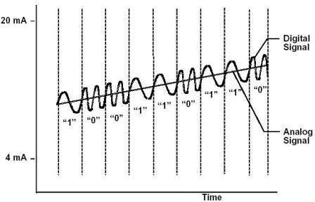
Figure 10. Analog Sensor Output via HART Protocol
The figure shows an analog signal, and a sine wave wriggles around it like a snake. This is a frequency modulated signal. But this is not a digital signal at all; it has yet to be recognized. It is noticeable in the figure that the frequency of the sinusoid when transmitting a logical zero is higher (2.2 KHz) than when transmitting a unit (1.2 KHz). The transmission of these signals is carried out by a current with an amplitude of ±0.5 mA of a sinusoidal shape.
It is known that the average value of the sinusoidal signal is zero, therefore, the transmission of digital information does not affect the output current of the 4...20 mA sensor. This mode is used when configuring sensors.
HART communication is accomplished in two ways. In the first case, the standard one, only two devices can exchange information over a two-wire line, while the output analog signal 4...20 mA depends on the measured value. This mode is used when configuring field devices (sensors).
In the second case, up to 15 sensors can be connected to a two-wire line, the number of which is determined by the parameters of the communication line and the power of the power supply. This is multipoint mode. In this mode, each sensor has its own address in the range 1...15, by which the control device accesses it.
The sensor with address 0 is disconnected from the communication line. Data exchange between the sensor and the control device in multipoint mode is carried out only by a frequency signal. The current signal of the sensor is fixed at the required level and does not change.
In the case of multipoint communication, data means not only the actual measurement results of the monitored parameter, but also a whole set of all kinds of service information.
First of all, these are sensor addresses, control commands, and configuration parameters. And all this information is transmitted over two-wire communication lines. Is it possible to get rid of them too? True, this must be done carefully, only in cases where the wireless connection cannot affect the safety of the controlled process.
It turns out that you can get rid of the wires. Already in 2007, the WirelessHART Standard was published; the transmission medium is the unlicensed 2.4 GHz frequency, on which many computer wireless devices operate, including wireless local networks. Therefore, WirelessHART devices can also be used without any restrictions. Figure 11 shows the WirelessHART wireless network.
Figure 11. Wireless network WirelessHART
These technologies have replaced the old analog current loop. But it does not give up its position, it is widely used wherever possible.
Connecting the current sensor to the microcontroller
Having familiarized ourselves with the basics of the theory, we can move on to the issue of reading, transforming and visualizing data. In other words, we will design a simple DC current meter.
The analog output of the sensor is connected to one of the ADC channels of the microcontroller. All necessary transformations and calculations are implemented in the microcontroller program. A 2-line character LCD indicator is used to display data.
Experimental design
To experiment with a current sensor, it is necessary to assemble the structure according to the diagram shown in Figure 8. The author used a breadboard and a microcontroller-based module for this (Figure 9).
The ACS712-05B current sensor module can be purchased ready-made (it is sold very inexpensively on eBay), or you can make it yourself. The capacitance of the filter capacitor is chosen to be 1 nF, and a blocking capacitor of 0.1 µF is installed for the power supply. To indicate power on, an LED with a quenching resistor is soldered. The power supply and output signal of the sensor are connected to the connector on one side of the module board, a 2-pin connector for measuring the flowing current is located on the opposite side.
For current measurement experiments, adjustable source DC voltage Let's connect to the current measuring terminals of the sensor through a series resistor 2.7 Ohm / 2 W. The sensor output is connected to the RA0/AN0 port (pin 17) of the microcontroller. A two-line character LCD indicator is connected to port B of the microcontroller and operates in 4-bit mode.
The microcontroller is powered by a voltage of +5 V, the same voltage is used as a reference for the ADC. The necessary calculations and transformations are implemented in the microcontroller program.
The mathematical expressions used in the conversion process are given below.
Current sensor sensitivity Sens = 0.185 V/A. With a supply Vcc = 5 V and a reference voltage Vref = 5 V, the calculated relationships will be as follows:
ADC output code


Hence
As a result, the formula for calculating the current is as follows:
Important note. The above relationships are based on the assumption that the supply voltage and reference voltage for the ADC are equal to 5 V. However, the last expression relating the current I and the ADC output code Count remains valid even if the power supply voltage fluctuates. This was discussed in the theoretical part of the description.
From the last expression it can be seen that the current resolution of the sensor is 26.4 mA, which corresponds to 513 ADC samples, which is one sample more than the expected result. Thus, we can conclude that this implementation does not allow the measurement of small currents. To increase resolution and sensitivity when measuring small currents, you will need to use an operational amplifier. An example of such a circuit is shown in Figure 10.
Microcontroller program
The PIC16F1847 microcontroller program is written in C language and compiled in the mikroC Pro environment (mikroElektronika). The measurement results are displayed on a two-line LCD indicator with an accuracy of two decimal places.
Exit
With zero input current, the ACS712 output voltage should ideally be strictly Vcc/2, i.e. The number 512 should be read from the ADC. The drift of the sensor output voltage by 4.9 mV causes the conversion result to shift by 1 least significant bit of the ADC (Figure 11). (For Vref = 5.0 V, the resolution of the 10-bit ADC will be 5/1024 = 4.9 mV), which corresponds to 26 mA of input current. Note that to reduce the influence of fluctuations, it is advisable to make several measurements and then average their results.
If the output voltage of the regulated power supply is set equal to 1 V, through
the resistor should carry a current of about 370 mA. The measured current value in the experiment is 390 mA, which exceeds correct result per one unit of the least significant bit of the ADC (Figure 12).
|
|
|
| Figure 12. | |

At a voltage of 2 V, the indicator will show 760 mA.
This concludes our discussion of the ACS712 current sensor. However, we did not touch upon one more issue. How to measure with this sensor alternating current? Keep in mind that the sensor provides an instantaneous response corresponding to the current flowing through the test leads. If the current flows in the positive direction (from pins 1 and 2 to pins 3 and 4), the sensitivity of the sensor is positive and the output voltage is greater than Vcc/2. If the current changes direction, the sensitivity will be negative and the output voltage of the sensor will drop below the Vcc/2 level. This means that when measuring an AC signal, the microcontroller's ADC must sample fast enough to be able to calculate the RMS value of the current.
Downloads
Source code of the microcontroller program and file for firmware -
Discrete sensors
This algorithm allows you to avoid impact when closing the mold, otherwise it can simply be broken into small pieces. The same change in speed occurs when opening the mold. Here two contact sensors are no longer enough.
Application of analog sensors
Figure 2. Wheatstone bridge
Connecting analog sensors

Analog sensor outputs


But, as a rule, a single sensor is not enough. Some of the most popular measurements are temperature and pressure measurements. The number of such points in modern factories can reach several tens of thousands. Accordingly, the number of sensors is also large. Therefore, several analog sensors are most often connected to one controller at once. Of course, not several thousand at once, it’s good if a dozen are different. Such a connection is shown in Figure 7.

Figure 7. Connecting multiple analog sensors to the controller
This figure shows how a voltage suitable for conversion to a digital code is obtained from a current signal. If there are several such signals, then they are not all processed at once, but are separated in time and multiplexed, otherwise a separate ADC would have to be installed on each channel.
For this purpose, the controller has a circuit switching circuit. The functional diagram of the switch is shown in Figure 8.

Figure 8. Analog sensor channel switch (picture clickable)
The current loop signals converted into voltage across the measuring resistor (UR1...URn) are fed to the input of the analog switch. The control signals alternately pass to the output one of the signals UR1...URn, which are amplified by the amplifier, and alternately arrive at the input of the ADC. The voltage converted into a digital code is supplied to the controller.
The scheme, of course, is very simplified, but it is quite possible to consider the principle of multiplexing in it. This is approximately how the module for inputting analog signals of MSTS controllers (microprocessor system of technical means) produced by the Smolensk PC “Prolog” was built.
The production of such controllers has long been discontinued, although in some places, far from the best, these controllers still serve. These museum exhibits are being replaced by controllers of new models, mostly imported (Chinese).
If the controller is mounted in a metal cabinet, it is recommended to connect the shielding braids to the cabinet grounding point. The length of connecting lines can reach more than two kilometers, which is calculated using the appropriate formulas. We won’t count anything here, but believe me, it’s true.
New sensors, new controllers
With the arrival of new controllers, new analog sensors also appeared that operate using the HART (Highway Addressable Remote Transducer) protocol, which translates as “Measuring transducer addressed remotely via a highway.”
The output signal of the sensor (field device) is an analog current signal in the range 4...20 mA, on which a frequency-modulated (FSK - Frequency Shift Keying) digital communication signal is superimposed.
It is known that the average value of the sinusoidal signal is zero, therefore, the transmission of digital information does not affect the output current of the 4...20 mA sensor. This mode is used when configuring sensors.
HART communication is accomplished in two ways. In the first case, the standard one, only two devices can exchange information over a two-wire line, while the output analog signal 4...20 mA depends on the measured value. This mode is used when configuring field devices (sensors).
In the second case, up to 15 sensors can be connected to a two-wire line, the number of which is determined by the parameters of the communication line and the power of the power supply. This is multipoint mode. In this mode, each sensor has its own address in the range 1...15, by which the control device accesses it.
The sensor with address 0 is disconnected from the communication line. Data exchange between the sensor and the control device in multipoint mode is carried out only by a frequency signal. The current signal of the sensor is fixed at the required level and does not change.
In the case of multipoint communication, data means not only the actual measurement results of the monitored parameter, but also a whole set of all kinds of service information.
First of all, these are sensor addresses, control commands, and configuration parameters. And all this information is transmitted via two-wire communication lines. Is it possible to get rid of them too? True, this must be done carefully, only in cases where the wireless connection cannot affect the safety of the controlled process.
These technologies have replaced the old analog current loop. But it does not give up its position, it is widely used wherever possible.
In the process of automating technological processes to control mechanisms and units, one has to deal with measurements of various physical quantities. This can be temperature, pressure and flow of liquid or gas, rotation speed, light intensity, information about the position of parts of mechanisms and much more. This information is obtained using sensors. Here, first, about the position of the parts of the mechanisms.
Discrete sensors
The simplest sensor is an ordinary mechanical contact: the door is opened - the contact opens, closed - it closes. Such a simple sensor, as well as the given operating algorithm, is often used in security alarms. For a mechanism with translational movement, which has two positions, for example a water valve, you will need two contacts: one contact is closed - the valve is closed, the other is closed - it is closed.
A more complex algorithm for translational movement has a mechanism for closing the thermoplastic mold of the automatic machine. Initially, the mold is open, this is the starting position. In this position, finished products are removed from the mold. Next, the worker closes the safety guard and the mold begins to close, and a new work cycle begins.
The distance between the halves of the mold is quite large. Therefore, at first the mold moves quickly, and at some distance before the halves close, the limit switch is triggered, the speed of movement decreases significantly and the mold closes smoothly.
Thus, contact based sensors are discrete or binary, have two positions, closed - open or 1 and 0. In other words, we can say that an event has occurred or not. In the example above, several points are “caught” by the contacts: the beginning of movement, the point of decreasing speed, the end of movement.
In geometry, a point has no dimensions, just a point and that's it. It can either be (on a piece of paper, in the trajectory of movement, as in our case) or it simply does not exist. Therefore, discrete sensors are used to detect points. Perhaps a comparison with a point is not very appropriate here, because for practical purposes they use the accuracy of the response of a discrete sensor, and this accuracy is much greater than the geometric point.
But mechanical contact itself is unreliable. Therefore, wherever possible, mechanical contacts are replaced by contactless sensors. The simplest option is reed switches: the magnet approaches, the contact closes. The accuracy of the reed switch leaves much to be desired; such sensors should only be used to determine the position of the doors.
Various contactless sensors should be considered a more complex and accurate option. If the metal flag entered the slot, the sensor was triggered. An example of such sensors is the BVK (Contactless Limit Switch) sensors of various series. The response accuracy (travel differential) of such sensors is 3 millimeters.
BVK series sensor
Figure 1. BVK series sensor
The supply voltage of the BVK sensors is 24V, the load current is 200mA, which is quite enough to connect intermediate relays for further coordination with the control circuit. This is how BVK sensors are used in various equipment.
In addition to BVK sensors, sensors of the types BTP, KVP, PIP, KVD, PISH are also used. Each series has several types of sensors, designated by numbers, for example, BTP-101, BTP-102, BTP-103, BTP-211.
All mentioned sensors are non-contact discrete, their main purpose is to determine the position of parts of mechanisms and assemblies. Naturally, there are many more of these sensors; it is impossible to write about them all in one article. Various contact sensors are even more common and are still widely used.
Application of analog sensors
In addition to discrete sensors, analog sensors are widely used in automation systems. Their purpose is to obtain information about various physical quantities, and not just in general, but in real time. More precisely, the conversion of a physical quantity (pressure, temperature, illumination, flow, voltage, current) into an electrical signal suitable for transmission via communication lines to the controller and its further processing.
Analog sensors are usually located quite far from the controller, which is why they are often called field devices. This term is often used in technical literature.
An analog sensor usually consists of several parts. The most important part is the sensitive element - the sensor. Its purpose is to convert the measured value into an electrical signal. But the signal received from the sensor is usually small. To obtain a signal suitable for amplification, the sensor is most often included in a bridge circuit - a Wheatstone bridge.
Wheatstone bridge
Figure 2. Wheatstone bridge
The original purpose of a bridge circuit is to accurately measure resistance. A DC source is connected to the diagonal of the AD bridge. A sensitive galvanometer with a midpoint, with zero in the middle of the scale, is connected to the other diagonal. To measure the resistance of the resistor Rx, by rotating the tuning resistor R2, you should achieve equilibrium of the bridge and set the galvanometer needle to zero.
The deviation of the instrument arrow in one direction or another allows you to determine the direction of rotation of resistor R2. The value of the measured resistance is determined by the scale combined with the handle of resistor R2. The equilibrium condition for the bridge is the equality of the ratios R1/R2 and Rx/R3. In this case, a zero potential difference is obtained between points BC, and no current flows through the galvanometer V.
The resistance of resistors R1 and R3 is selected very precisely, their spread should be minimal. Only in this case, even a small imbalance of the bridge causes a fairly noticeable change in the voltage of the diagonal BC. It is this property of the bridge that is used to connect sensitive elements (sensors) of various analog sensors. Well, then everything is simple, a matter of technique.
To use the signal received from the sensor, it requires further processing - amplification and conversion into an output signal suitable for transmission and processing by the control circuit - the controller. Most often, the output signal of analog sensors is current (analog current loop), less often voltage.
Why current? The fact is that the output stages of analog sensors are built on the basis of current sources. This allows you to get rid of the influence of the resistance of connecting lines on the output signal and use long connecting lines.
Further conversion is quite simple. The current signal is converted into voltage, for which it is enough to pass the current through a resistor of known resistance. The voltage drop across the measuring resistor is obtained according to Ohm's law U=I*R.
For example, for a current of 10 mA on a resistor with a resistance of 100 Ohm, the voltage will be 10 * 100 = 1000 mV, as much as 1 volt! In this case, the output current of the sensor does not depend on the resistance of the connecting wires. Within reasonable limits, of course.
Connecting analog sensors
The voltage obtained at the measuring resistor can be easily converted into a digital form suitable for input into the controller. The conversion is performed using analog-to-digital converters (ADCs).
Digital data is transmitted to the controller by serial or parallel code. It all depends on the specific switching circuit. A simplified connection diagram for an analog sensor is shown in Figure 3.
Connecting an analog sensor
Figure 3. Connecting an analog sensor (click on the picture to enlarge)
Actuators are connected to the controller, or the controller itself is connected to a computer included in the automation system.
Naturally, analog sensors have a complete design, one of the elements of which is a housing with connecting elements. As an example, Figure 4 shows the appearance of an overpressure sensor of the Zond-10 type.
Overpressure sensor Zond-10
Figure 4. Overpressure sensor Zond-10
At the bottom of the sensor you can see the connecting thread for connecting to the pipeline, and on the right under the black cover there is a connector for connecting the communication line with the controller.
The threaded connection is sealed using a washer made of annealed copper (included in the delivery package of the sensor), and not by winding it with fum tape or flax. This is done so that when installing the sensor, the sensor element located inside is not deformed.
Analog sensor outputs
According to the standards, there are three ranges of current signals: 0...5mA, 0...20mA and 4...20mA. What is their difference, and what are their features?
Most often, the dependence of the output current is directly proportional to the measured value, for example, the higher the pressure in the pipe, the greater the current at the sensor output. Although sometimes inverse switching is used: a larger output current corresponds to the minimum value of the measured quantity at the sensor output. It all depends on the type of controller used. Some sensors even have a switch from direct to inverse signal.
The output signal in the 0...5mA range is very small and therefore susceptible to interference. If the signal of such a sensor fluctuates while the value of the measured parameter remains unchanged, then there is a recommendation to install a capacitor with a capacity of 0.1...1 μF in parallel with the sensor output. The current signal in the range 0...20mA is more stable.
But both of these ranges are bad because zero at the beginning of the scale does not allow us to unambiguously determine what happened. Or did the measured signal actually reach zero level, which is possible in principle, or did the communication line simply break? Therefore, if possible, they try to avoid using these ranges.
The signal from analog sensors with an output current in the range of 4...20 mA is considered more reliable. Its noise immunity is quite high, and the lower limit, even if the measured signal has a zero level, will be 4 mA, which allows us to say that the communication line is not broken.
Another good feature of the 4...20mA range is that sensors can be connected using only two wires, since this is the current that powers the sensor itself. This is its current consumption and at the same time a measuring signal.
The power supply for sensors in the 4...20mA range is turned on, as shown in Figure 5. At the same time, Zond-10 sensors, like many others, according to their data sheet have a wide supply voltage range of 10...38V, although stabilized sources with a voltage of 24V are most often used.
Connecting an analog sensor with an external power supply
Figure 5. Connecting an analog sensor with an external power supply
This diagram contains the following elements and symbols. Rsh is the measuring shunt resistor, Rl1 and Rl2 are the resistance of the communication lines. To increase the measurement accuracy, a precision measuring resistor should be used as Rsh. The flow of current from the power source is shown by arrows.
It is easy to see that the output current of the power supply passes from the +24V terminal, through the line Rl1 reaches the sensor terminal +AO2, passes through the sensor and through the output contact of the sensor - AO2, connecting line Rl2, the resistor Rsh returns to the -24V power supply terminal. That's it, the circuit is closed, the current flows.
If the controller contains a 24V power supply, then connecting a sensor or measuring transducer is possible according to the diagram shown in Figure 6.
Connecting an analog sensor to a controller with internal power supply
Figure 6. Connecting an analog sensor to a controller with internal power supply
This diagram shows one more element - the ballast resistor Rb. Its purpose is to protect the measuring resistor in the event of a short circuit in the communication line or a malfunction of the analog sensor. Installation of resistor Rb is optional, although desirable.
In addition to various sensors, measuring transducers also have a current output, which are used quite often in automation systems.
A measuring transducer is a device for converting voltage levels, for example, 220V or a current of several tens or hundreds of amperes into a current signal of 4...20mA. Here, the level of the electrical signal is simply converted, and not the representation of some physical quantity (speed, flow, pressure) in electrical form.
But, as a rule, a single sensor is not enough. Some of the most popular measurements are temperature and pressure measurements. The number of such points in modern production can reach several ten
Read also
- Types of wall lamps and features of their use
- About potential difference, electromotive force and voltage
- What can be determined by the meter, except electricity consumption
- On the criteria for assessing the quality of electrical products
- What is better for a private home - single-phase or three-phase input?
- How to choose a voltage stabilizer for a country house
- Peltier effect: the magical effect of electric current
- The practice of wiring and connecting TV cables in an apartment - features of the process
- Electrical wiring problems: what to do and how to fix them?
- T5 fluorescent lamps: prospects and problems of application
- Retractable socket blocks: practice of use and connection
- Electronic amplifiers. Part 2. Audio amplifiers
- Correct operation of electrical equipment and wiring in a country house
- Key points about using safe voltage at home
- Necessary tools and devices for beginners to study electronics
- Capacitors: purpose, device, principle of operation
- What is transient contact resistance and how to deal with it
- Voltage relays: what are they, how to choose and connect?
- What is better for a private home - single-phase or three-phase input?
- Capacitors in electronic circuits. Part 2. Interstage communication, filters, generators
- How to ensure comfort when the power grid is insufficient
- When buying a machine in a store, how can you be sure that it is in good working order?
- How to choose wire cross-section for 12 volt lighting networks
- Method for connecting a water heater and pump when the network power is insufficient
- Inductors and magnetic fields. Part 2. Electromagnetic induction and inductance
- Operational amplifiers. Part 2: Ideal Op-Amp
- What are microcontrollers (purpose, device, software)
- Extending the life of a compact fluorescent lamp (housekeeper)
- Circuits for switching operational amplifiers without feedback
- Replacing the electrical distribution panel of an apartment
- Why can't you combine copper and aluminum in electrical wiring?